Precision Engineering in Oil & Gas Tank Fabrication
In the heavy industry sector, particularly in the manufacturing of pressure vessels and storage units, the transition toward high-density energy sources has redefined production benchmarks. The application of a Fiber Laser Cutting Machine provides a level of thermal control and mechanical precision that traditional mechanical methods cannot replicate. For oil and gas tanks, where structural integrity is non-negotiable, the fiber laser serves as the primary tool for processing thick-section carbon steel and stainless steel alloys.
The industrial engineering focus here is on the elimination of variance. Unlike legacy tools that require manual layout and physical templates, the fiber laser system operates on a direct CAD-to-Part workflow. This ensures that every aperture, manway, and nozzle fit-up point is executed with a tolerance often exceeding +/- 0.05mm. In a sector where safety margins are governed by stringent ASME and API codes, this level of repeatability is essential for minimizing downstream assembly complications.
The Role of Laser Seam Tracking in Geometric Accuracy
Large-scale tank production often involves the processing of pre-curved plates or components that may exhibit slight material irregularities due to rolling or transport. This is where Laser Seam Tracking becomes a critical component of the cutting assembly. Rather than relying on a static coordinate system, the cutting head is equipped with high-speed optical sensors that scan the material surface in real-time.
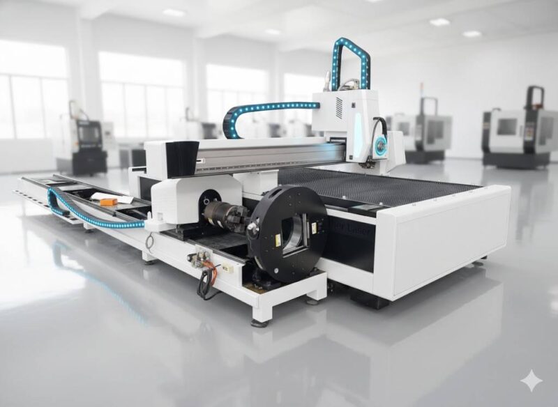
These sensors utilize laser triangulation to detect the exact position and topography of the workpiece. As the gantry moves, the system compensates for any deviations in the plate’s height or lateral positioning. This active feedback loop ensures that the focal point of the fiber laser remains constant relative to the material surface. By maintaining a stable standoff distance, the machine prevents kerf distortion and ensures a perpendicular cut edge, which is vital for the subsequent fit-up of tank shells and heads.
Three-in-One Processing: Punch, Mark, and Cut
One of the most significant efficiency gains in modern industrial engineering is the consolidation of manufacturing steps. A Fiber Laser Cutting Machine specialized for the oil and gas industry is not merely a cutting tool; it is a multi-functional processing center. The software logic allows for a sequential execution of three distinct operations without the need to unclamp or reposition the workpiece.
First, the laser can perform “punching” or piercing operations using ultra-short pulse bursts. This creates high-precision pilot holes or entry points with minimal thermal spread. Second, the system executes laser marking. This involves surface-level etching of part numbers, heat numbers, and alignment markers. Marking is critical for traceability in the oil and gas sector, ensuring that every plate can be tracked back to its mill certification. Finally, the machine transitions to the high-power cutting phase, utilizing a continuous wave beam to profile the component at high velocities.
Eliminating Secondary Operations and Grinding
Traditional cutting methods often leave behind a thick dross or a heavy oxide layer that requires manual grinding before any further assembly can occur. In an industrial engineering capacity, grinding represents “non-value-added time.” It increases labor costs, consumes abrasives, and introduces ergonomic risks to the workforce.
High-power fiber lasers, particularly those operating in the 12kW to 30kW range, utilize high-pressure assist gases (typically Oxygen or Nitrogen) to evacuate molten material instantaneously. The result is a clean, dross-free edge that is ready for assembly immediately upon completion of the cut. The narrow Heat-Affected Zone (HAZ) produced by the fiber laser ensures that the metallurgical properties of the tank walls remain intact, preventing the embrittlement that can lead to stress corrosion cracking in volatile environments.
Technical Optimization of the Optical Path
The core of the Automated Precision Cutting process lies in the delivery of the laser beam. Fiber lasers deliver energy through a flexible silica fiber, which is then collimated and focused by a series of lenses within the cutting head. For oil and gas applications involving heavy plates, the optical system must be capable of varying the beam diameter and mode.
By adjusting the focal position, the machine can optimize the power density for different thicknesses. A “thin” beam is used for high-speed marking and punching, while a “wider” beam profile is often employed for thicker plates to facilitate efficient melt ejection. This versatility allows a single machine to handle everything from thin internal baffles to heavy external tank shells, maximizing the Return on Investment (ROI) for the fabrication facility.
Integration with Industry 4.0 and CNC Logic
The modern fiber laser system is fully integrated into the factory’s digital ecosystem. Through advanced CNC controllers, the machine provides real-time data on gas consumption, power usage, and cutting time per part. This data is invaluable for industrial engineers tasked with cost estimation and production scheduling.
Furthermore, the laser seam tracking system contributes to the “digital twin” of the production process. By recording the topographical data of each plate, the system can provide a quality report that confirms the part was cut within the required geometric tolerances. This level of digital verification is becoming a standard requirement for major contractors in the oil and gas infrastructure sector.
Safety and Environmental Considerations
From an operational standpoint, fiber laser machines are significantly more energy-efficient than their CO2 predecessors, with wall-plug efficiencies exceeding 30%. This reduces the carbon footprint of the manufacturing facility—a growing concern in the energy sector. Additionally, because the cutting process is fully enclosed and highly controlled, the emission of particulate matter is easily managed through integrated dust extraction and filtration systems.
The elimination of the grinding process also contributes to a safer work environment by reducing noise pollution and airborne metallic dust. By automating the tracking and cutting phases, the operator is removed from the immediate vicinity of the high-energy beam, further enhancing the safety profile of the tank fabrication shop.
Summary of Engineering Benefits
The implementation of a fiber laser system with integrated seam tracking represents a fundamental shift in how Oil & Gas Tanks are manufactured. The primary benefits include:
- Superior edge quality that eliminates the need for secondary grinding or edge preparation.
- Real-time compensation for material irregularities via laser seam tracking, ensuring perfect fit-up.
- Consolidated punching, marking, and cutting operations that reduce material handling and cycle times.
- Minimal thermal distortion, preserving the mechanical integrity of high-strength alloys.
- Full digital integration for enhanced traceability and quality assurance.
In conclusion, for manufacturers aiming to remain competitive in the global energy infrastructure market, the adoption of fiber laser technology is a strategic necessity. The combination of precision, speed, and automation addresses the primary challenges of tank fabrication while setting a new standard for industrial excellence.
-


LT240S tube laser cutting machine
-
LT120S tube laser cutting machine
-
Sale

Tank Fillet Welding Machine
Original price was: $1,000.00.$900.00Current price is: $900.00. -
Sale

MAK100 tube laser cutting machine
Original price was: $5,500.00.$5,000.00Current price is: $5,000.00. -

portable plasma air cutting machine
$1,200.00 -

2in1 fiber laser cutting machine
-

Air cooling Laser welding machine
-

HF h beam laser cutting machine
-

LT240 laser cutting machine
-

Laser welding machine
-


Cobot Welding Station
-

Gantry welding robot solution
-

Tracked Wheeled AGV Welding robot
-

LFH6020 Fiber laser cutting machine
-
LFP6020
-

robotic welidng machine
Advanced Fiber Laser Tube Processing Technology
Our CNC Fiber Laser Tube Cutting systems revolutionize metal fabrication by integrating high-precision cutting, punching, and profiling into a single automated workflow. Designed for versatility, this technology handles a wide array of profiles including Round, Square, Rectangular, and Oval tubes, as well as complex L-shaped and U-shaped channels.
- Precision Punching: High-speed hole punching with micron-level accuracy, eliminating the need for mechanical drilling or die-stamping.
- Complex Profiling: Advanced 3D pathing allows for intricate interlocking joints and specialized notch cuts, ideal for structural frames.
- High Material Efficiency: Intelligent nesting software minimizes scrap, reducing raw material costs across large production runs.
- Clean Finish: Delivers oxide-free, burr-free edges that require zero secondary grinding before welding.

Seamlessly processing multiple profiles with consistent precision.
Global Delivery & Logistics


From our high-tech manufacturing facility directly to your global site. PCL WeldCut ensures secure packaging, professional handling, and reliable international logistics to safeguard your equipment throughout the entire journey.