The Cantilever Welding Robot solution is engineered to enhance precision and efficiency in welding applications across various industries. Featuring advanced robotics technology, this system offers exceptional flexibility and adaptability, allowing for seamless integration into existing manufacturing processes. With its robust design and automated capabilities, the Cantilever Welding Robot significantly reduces production time while maintaining superior weld quality, ensuring optimal performance and reliability.
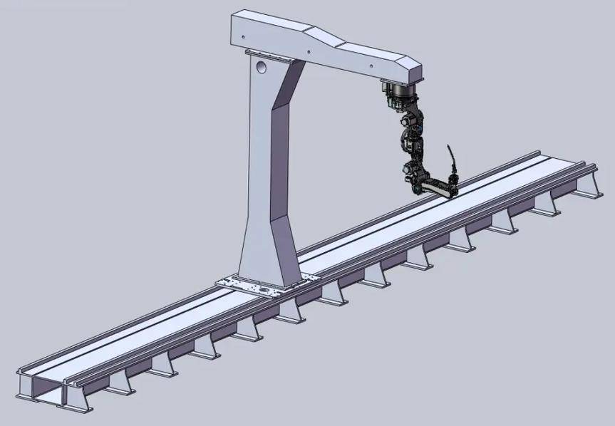
The PCL Cantilever Welding Robot Solution is a specialized automated system designed for large-scale workpieces and structural steel components. Featuring a horizontal overhanging arm extended from a robust vertical column, this design allows the welding head to reach over complex structures such as H-beams, heavy plates, and box girders. Unlike enclosed systems, the cantilever configuration leaves one side of the workspace completely open, making it the ideal choice for facilities using overhead cranes for material handling.
▶ Cantilever System in Action
Watch the high-precision tracking and seamless welding of structural steel components.
Technical Mastery & Parameters
| Model | Cantilever 500A (7-Axis Integration) |
| Arm Span / Reach | 2000mm (Fully Customizable) |
| Travel Rail Length | Standard 9M / 12M (Extended Rail Available) |
| Positioning Accuracy | ±0.05mm |
| Sensing Technology | 3D Laser Vision / Real-time Seam Tracking |
Why Choose Cantilever Design?
Unmatched Loading Accessibility
The single-sided column design ensures that the front and opposite side of the workstation remain unobstructed. This allows for seamless crane integration, crucial for heavy structural steelwork.
Multi-Axis Synergy
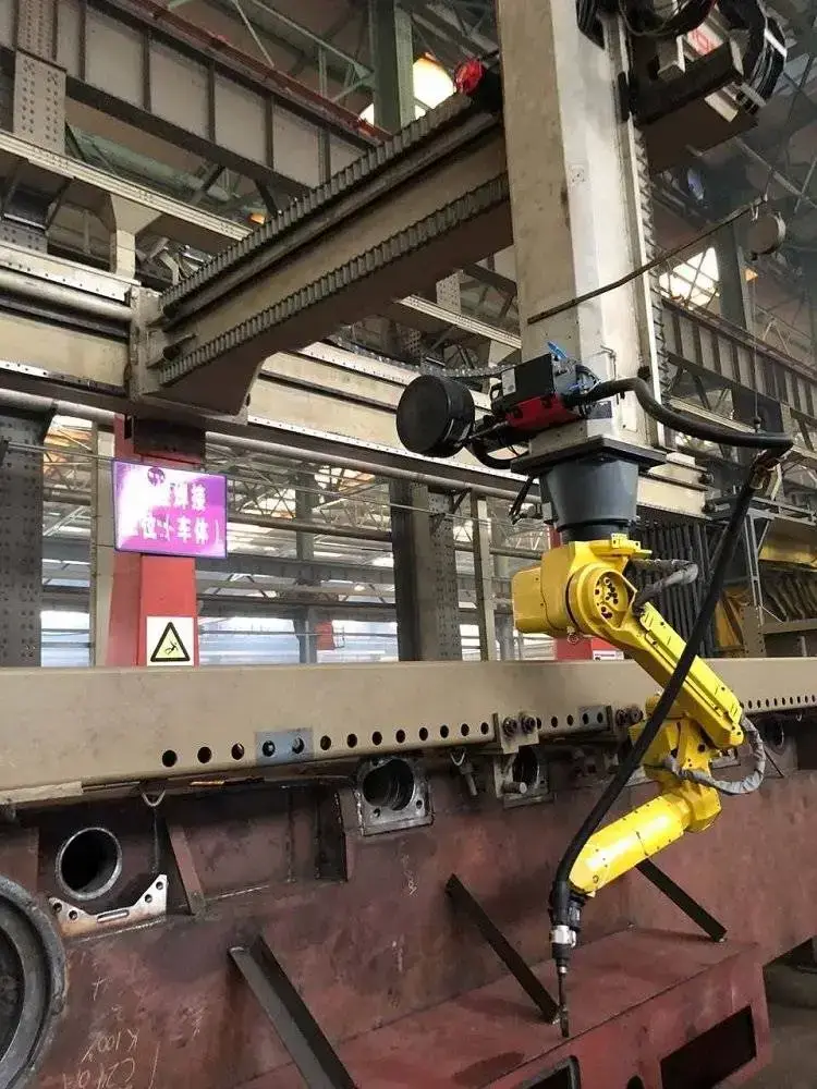
Synchronized 7-axis movement (6-axis arm + linear track) performs continuous welds along 12+ meter beams without interruption, maintaining perfect heat input control.
Target Industries
The Cantilever Welding Solution is specialized for heavy fabrication:
- H-Beams & I-Beams
- Bridge Truss Structures
- Shipbuilding Stiffeners
- Heavy Earthmover Chassis
- Custom Box Girders
- Industrial Crane Arms
Optimize Your Heavy Steel Fabrication
Ready to increase your arc-on time? Contact our engineers for a custom layout plan and a technical proposal.
Technical Mastery & Parameters
| Model | GR-WL500 (7-Axis Integration) |
| Arm Span / Reach | 2000mm (Fully Customizable) |
| Travel Rail Length | Standard 9M / 12M (Extended Rail Available) |
| Positioning Accuracy | ±0.05mm |
| Sensing Technology | 3D Laser Vision / Real-time Seam Tracking |
Why Choose Cantilever Design?
Unmatched Loading Accessibility
The single-sided column design ensures that the front and opposite side of the workstation remain unobstructed. This allows for seamless integration with overhead cranes, crucial for moving heavy structural steelwork.
Multi-Axis Synergy
Combining a 6-axis robotic arm with a motorized linear track creates a 7-axis (or more) synchronized system. It can perform continuous high-quality welds along 12+ meter beams without stopping.
Intelligent Path Correction
Equipped with high-precision 3D cameras and laser sensors, the system automatically corrects the welding path to compensate for material warping or slight positioning errors.
Advanced Programming: OLP vs. Teaching-Free
| Feature | Off-line Programming (OLP) | Teaching-Free System |
|---|---|---|
| Core Method | PC-Based 3D CAD Simulation | AI Vision & Laser Scanning |
| Uptime Benefit | Program while the robot welds | No manual coding required |
| Best Application | Massive batch production | Custom / One-off structural parts |
Target Industries
The Cantilever Welding Solution is the gold standard for heavy fabrication:
- Structural Steel (H-Beams)
- Shipbuilding & Marine Panels
- Heavy Earthmovers & Cranes
- Bridge Truss Welding
- Box Girders & Plate Joining
- Railway Carriage Bases
Frequently Asked Questions
Q1: What is the advantage of a cantilever over a gantry system?
A cantilever system provides more space for loading. Since it only has one supporting column on one side, large workpieces can be moved in and out more freely via crane from the front or side.
Q2: Can the system be customized for extra-long workpieces?
Absolutely. The travel rail (linear track) is modular and can be extended to 18 meters, 24 meters, or more to match the length of your structural beams.
Optimize Your Heavy Steel Fabrication
Every factory floor has different requirements. Contact PCL engineers for a tailored cantilever layout and free technical consultation.

Advanced Programming: OLP vs. Teaching-Free System
For large-scale gantry welding, manual "point-to-point" teaching is inefficient. PCL offers two cutting-edge solutions to minimize downtime and maximize precision. Understanding the difference is key to choosing the right automation level for your factory.
Off-line Programming (OLP)
OLP allows engineers to create welding paths in a 3D virtual environment using CAD data (STEP/IGES).
- Zero Downtime: Program the next job on a PC while the robot is still welding.
- Collision Detection: Simulates the gantry movement to prevent accidents in a virtual space.
- Best For: Complex workpieces with high repeat rates and detailed weld joints.
Teaching-Free Welding System
Uses 3D laser scanning or vision sensors to "see" the workpiece and generate paths automatically without any CAD data.
- Instant Setup: No manual coding or 3D modeling required; just scan and weld.
- High Flexibility: Ideal for "One-off" parts where every workpiece is slightly different.
- Real-time Adaptation: Automatically compensates for thermal distortion and fit-up gaps.
- Best For: Custom fabrication, repairs, and low-volume/high-mix production.
| Feature | Off-line Programming (OLP) | Teaching-Free System |
|---|---|---|
| Input Required | CAD 3D Models | 3D Laser Scanning |
| Programming Time | Minutes to Hours (Off-site) | Seconds (On-site) |
| Ideal Production | Mass Production / Batch Work | Custom / Single Unit Work |
Related products


Watch Related Videos
Frequently Asked Questions
Q1: What is the maximum workpiece size a gantry robot can handle?
The primary advantage of a gantry system is its scalability. Unlike fixed-base robots, the gantry rail length can be extended from 6 meters to over 30 meters. We customize the X, Y, and Z travel strokes based on your specific components, such as trailer chassis or large pressure vessels.
Q2: How does the robot handle material deviations or heat deformation?
For large workpieces, we recommend integrating Laser Seam Tracking or Arc Sensors. These technologies allow the robot to detect the actual weld joint position in real-time and adjust the torch path automatically, compensating for thermal distortion or fit-up tolerances.
Q3: Which robot brands are compatible with the PCL Gantry System?
Our gantry structures are highly flexible and can be integrated with leading international brands including Fanuc, ABB, Yaskawa, and KUKA, as well as our proprietary PCL robotic arms. We provide the full integration including the synchronized 7th or 8th external axes.
Q4: Is it difficult to program a gantry robot for complex large structures?
Not at all. We offer Off-line Programming (OLP) software. This allows your engineers to simulate the welding process and generate code on a PC using CAD data, significantly reducing machine downtime and preventing potential collisions before the physical welding starts.
Q5: Can one gantry system manage multiple welding stations?
Yes. A common configuration is a dual-station setup. While the robot is welding at Station A, operators can safely load or unload workpieces at Station B. This maximizes the robot's "Arc-on Time" and ensures continuous production flow.
