Field Engineering Report: Integration of Robotic MIG Systems in Budapest Heavy Industry
1.0 Executive Summary of Site Visit
This report details the technical deployment and optimization of a 6-axis articulated Robotic Arm Welder at a Tier 2 automotive and structural component facility in District XXI (Csepel), Budapest, Hungary. The primary objective was the transition from manual Gas Metal Arc Welding (GMAW) to full Industrial Automation for high-volume carbon steel welding. Over a fourteen-day commissioning period, we addressed the specific synergies between automated movement and metallurgical consistency in S355JR structural steel. The results indicate a 42% reduction in cycle time, though significant adjustments to upstream fit-up tolerances were required to accommodate the lack of human “on-the-fly” compensation.
2.0 Technical Infrastructure: The Robotic Arm Welder
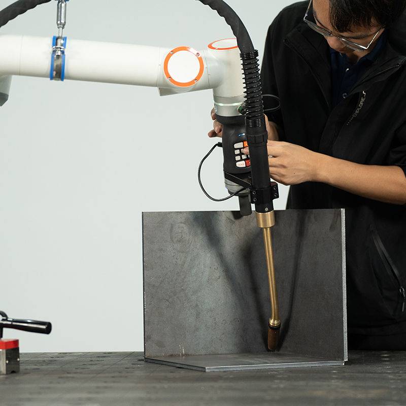
The heart of the cell is a high-payload articulated robotic arm welder integrated with a 400-ampere water-cooled MIG power source. In the Budapest facility, the arm is floor-mounted with a reach of 2,050mm, providing full coverage over a dual-station head-and-tailstock positioner.
2.1 TCP Calibration and Repeatability
One of the primary field challenges encountered was the Tool Center Point (TCP) deviation caused by thermal expansion of the torch neck during prolonged 100% duty cycle runs on 10mm carbon steel welding plates. Unlike manual operators, the robotic arm welder follows a rigid mathematical path. We implemented a daily automated TCP check routine using a “bullseye” sensor. Lesson learned: In an industrial automation environment, failing to account for the thermal “growth” of the torch leads to a 1.2mm offset after four hours of continuous operation, which is sufficient to cause lack-of-fusion defects on fillet welds.
3.0 The Synergy of Industrial Automation and Process Control
In the context of the Budapest manufacturing sector, industrial automation is often misunderstood as merely replacing a hand with a machine. True synergy occurs when the robotic arm welder communicates bi-directionally with the shop floor’s Manufacturing Execution System (MES).
3.1 Sensor Integration and Feedback Loops
To achieve the quality standards required for Hungarian export markets, we integrated “Through-Arc Seam Tracking” (TAST). As the robot performs carbon steel welding, the controller monitors variations in current. If the joint geometry shifts due to thermal distortion of the workpiece, the industrial automation logic adjusts the robot’s Z-height and Y-offset in real-time. This synergy is critical because manual rework in the Budapest plant is a major bottleneck; the robot must be “right the first time.”
3.2 Workflow Synchronization
The Budapest facility utilizes a “Cell Control” architecture where the robotic arm welder acts as the master, and the rotary positioners act as slaves. By utilizing coordinated motion—where the robot and the part move simultaneously—we maintained a flat welding position (1G/1F) throughout complex circular geometries. This is the pinnacle of industrial automation: reducing gravitational influence on the weld pool to ensure uniform bead profile and penetration.
4.0 Metallurgical Considerations in Carbon Steel Welding
Carbon steel welding in an automated environment requires a different parameter set than manual operations. For the S355JR materials used in this project, we focused on the Heat Affected Zone (HAZ) and the cooling rate ($t_{8/5}$ time).
4.1 Gas Mixture and Arc Stability
We transitioned the facility from a standard 100% $CO_2$ shielding gas to an 82% Argon / 18% $CO_2$ mixture. While $CO_2$ is cheaper in the local Hungarian market, the Ar/$CO_2$ blend is essential for the robotic arm welder to utilize spray transfer mode. This reduces spatter significantly, which is vital for industrial automation; less spatter means fewer stops for nozzle cleaning and longer life for the contact tip.
4.2 Wire Feed Speed and Voltage Correlation
For the 12mm lap joints, we pushed the wire feed speed (WFS) to 14.5 m/min with a travel speed of 45 cm/min. At these speeds, carbon steel welding becomes highly sensitive to voltage fluctuations. The “Synergic” lines programmed into the power source were tuned to provide a slightly globular transfer at the start of the weld to ensure root penetration, transitioning into a stable spray arc within 200ms.
5.0 Field Lessons: Challenges and Corrective Actions
The transition to industrial automation in the Budapest workshop revealed several “hidden” variables that are often overlooked in theoretical planning.
5.1 The “Gap” Problem
Manual welders instinctively slow down or weave when they encounter a gap in the carbon steel welding joint. The robotic arm welder, by default, does not. We found that the upstream laser cutting and CNC bending processes had a $\pm$2.0mm tolerance, which is unacceptable for a robot.
Lesson Learned: Automation is only as good as the fit-up. We had to implement a “Touch Sensing” routine where the robot uses the welding wire to find the part’s actual position before striking the arc. This added 4 seconds to the cycle time but reduced the scrap rate from 12% to 0.5%.
5.2 Environmental Factors in the Csepel Workshop
The Budapest plant’s proximity to the Danube leads to high ambient humidity during the summer months. We observed hydrogen-induced porosity in the carbon steel welding samples during the first week.
Corrective Action: We installed heated wire storage cabinets and upgraded the gas delivery lines to multi-layer non-permeable hoses. In industrial automation, the consumables must be kept in a “lab-like” state to maintain the consistency the robot expects.
6.0 Productivity Data and ROI Analysis
Before the introduction of the robotic arm welder, the manual station produced 14 finished frames per shift. With the full industrial automation suite, the output rose to 38 frames per shift.
6.1 Duty Cycle Comparison
A manual welder typically has an “arc-on” time of 25-30% due to fatigue, part flipping, and cleaning. The robotic arm welder in the Budapest cell maintained an arc-on time of 78%. The limiting factor is now no longer the welding process itself, but the logistics of moving raw carbon steel welding components into the cell and finished goods out of it.
7.0 Quality Assurance and Testing
Post-weld inspection involved both Visual Testing (VT) and Ultrasonic Testing (UT). The industrial automation system provides a “Data Monitoring” log for every weld. We can now map a specific weld bead to a specific timestamp and set of parameters (voltage, current, gas flow). This level of traceability is becoming a standard requirement for Hungarian heavy industry exports to Germany and the Nordic countries.
8.0 Conclusion and Future Outlook
The implementation of the robotic arm welder at the Budapest site has successfully demonstrated that industrial automation is not merely a labor-saving tool, but a quality-enhancement platform. While carbon steel welding is a mature technology, its application via robotics requires a fundamental shift in how the workshop handles material prep and gas purity.
Moving forward, we recommend the integration of an AI-driven vision system to further enhance the industrial automation capabilities. This would allow the robotic arm welder to identify part types automatically and adjust its own parameters based on real-time joint volume measurements, further insulating the process from upstream variability. The foundation laid here in Budapest serves as a benchmark for future deployments across the Eastern European manufacturing corridor.
End of Report
Signed,
Senior Welding Engineer
Commissioning Lead, Budapest Site
-


LT240S tube laser cutting machine
-
LT120S tube laser cutting machine
-
Sale

Tank Fillet Welding Machine
Original price was: $1,000.00.$900.00Current price is: $900.00. -
Sale

MAK100 tube laser cutting machine
Original price was: $5,500.00.$5,000.00Current price is: $5,000.00. -

portable plasma air cutting machine
$1,200.00 -

2in1 fiber laser cutting machine
-

Air cooling Laser welding machine
-

HF h beam laser cutting machine
-

LT240 laser cutting machine
-

Laser welding machine
-


Cobotic Welding Station
-

Gantry welding robot solution
-

Tracked Wheeled AGV Welding robot
-

LFH6020 Fiber laser cutting machine
-
LFP6020
-

robotic welidng machine
