Engineering Review: Precision CMT MIG/MAG Welding Robot – Krakow, Poland
In this article
- Field Report: Deployment of Precision CMT MIG/MAG Welding Robot – Krakow Industrial…
- 1.0 Introduction and Scope of Site Visit
- 2.0 Technical Configuration: The MIG/MAG Welding Robot
- 3.0 Implementing Advanced Arc Welding Solutions
- 4.0 Addressing the Challenges of Copper Components Welding
- 5.0 Synergy in the Krakow Workshop: Robot and Process Integration
- 6.0 Lessons Learned and Engineering Recommendations
- 7.0 Conclusion
Field Report: Deployment of Precision CMT MIG/MAG Welding Robot – Krakow Industrial Zone
1.0 Introduction and Scope of Site Visit
This report summarizes the technical commissioning and optimization of the automated welding cell at the Krakow facility, focused on the production of high-conductivity electrical busbars. The primary objective was the integration of a 6-axis **MIG/MAG Welding Robot** equipped with Cold Metal Transfer (CMT) technology to replace legacy manual TIG processes.
The scope involved calibrating the **Arc Welding Solutions to handle the specific thermal demands of Copper Components welding**, particularly Oxygen-Free High Conductivity (OFHC) copper and C11000 ETP copper. As a senior engineer, my focus was on mitigating the extreme thermal dissipation inherent in copper while maintaining a stable arc at the low-voltage thresholds required for thin-gauge material.
2.0 Technical Configuration: The MIG/MAG Welding Robot
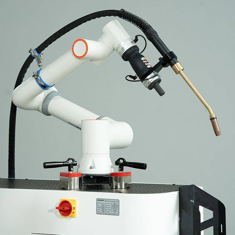
The core of the cell is a high-speed, 6-axis articulated MIG/MAG Welding Robot integrated with a Fronius TPS 400i CMT power source. Unlike standard spray-transfer or globular-transfer systems, this configuration utilizes a digitalized “push-pull” wire feed system.
2.1 Kinematic Calibration and Path Precision
In the Krakow workshop, we identified a recurring deviation in the Tool Center Point (TCP) during high-duty cycles. The robot’s repeatability was rated at ±0.05mm, but thermal expansion of the copper workpieces and the torch neck during prolonged Copper Components welding caused a drift of nearly 0.4mm. We implemented a scheduled “Torch Clean and Check” routine every 50 cycles, utilizing a mechanical wire cutter and gas nozzle reamer to re-index the TCP. This ensured that the MIG/MAG Welding Robot maintained consistent bead placement on the 3mm fillet joints.
2.2 Wire Feed Dynamics
We utilized a 1.2mm CuCrZr (Copper-Chromium-Zirconium) wire. The primary challenge with a MIG/MAG Welding Robot in this context is the softness of the filler metal. Traditional drive rolls caused “bird-nesting.” We transitioned to U-grooved ceramic rollers and a Teflon-lined conduit to minimize friction, ensuring the CMT oscillating wire frequency (up to 70 Hz) remained synchronized with the power source’s waveform.
3.0 Implementing Advanced Arc Welding Solutions
In the context of the Krakow facility, “Arc Welding Solutions” refers to the holistic synergy between the power source, the shielding gas chemistry, and the real-time sensor feedback loop.
3.1 Shielding Gas Optimization
Initial tests using pure Argon resulted in insufficient penetration and a “cold lap” appearance on the copper substrates. The high thermal conductivity of copper (approx. 400 W/m·K) necessitates a hotter arc than steel. We modified our Arc Welding Solutions by introducing a 30% Helium / 70% Argon mix. The Helium component increased the ionization potential, broadening the plasma arc and deepening the penetration profile without requiring an increase in wire feed speed, which would have risked burn-through on 2mm sections.
3.2 The CMT (Cold Metal Transfer) Waveform
The “Cold” in CMT is relative, but vital for Copper Components welding. By mechanically retracting the wire when a short circuit is detected, the MIG/MAG Welding Robot can detach droplets at near-zero current. In Krakow, we tuned the “Boost” and “Wait” phases of the CMT cycle. A higher boost current was required to overcome the initial heat sink of the copper, followed by a rapid reduction to prevent the collapse of the weld pool.
4.0 Addressing the Challenges of Copper Components Welding
Copper Components welding is notoriously difficult due to its high reflectivity and thermal diffusivity. The Krakow project involved joining heavy-gauge busbars to thin-walled connectors, creating a massive heat-sink imbalance.
4.1 Managing Thermal Conductivity
To prevent “cold starts,” we programmed a pre-heating pass using the MIG/MAG Welding Robot’s arc in a non-consumable mode (low amperage, high travel speed) before initiating the actual weld bead. This 150°C localized pre-heat allowed for a consistent wetting of the weld toe. Without this, the first 10mm of the weld showed significant lack-of-fusion defects during X-ray inspection.
4.2 Porosity Mitigation
Copper is highly susceptible to hydrogen porosity. We discovered that the ambient humidity in the Krakow facility, particularly during the transition to autumn, was contaminating the gas lines. Our Arc Welding Solutions were updated to include a point-of-use gas dryer and a transition from rubber to stainless-steel braided gas hoses to prevent moisture permeation. Post-implementation, macro-etch tests showed a 95% reduction in gas pores.
5.0 Synergy in the Krakow Workshop: Robot and Process Integration
The success of this deployment relied on the synergy between the MIG/MAG Welding Robot and the specialized Arc Welding Solutions. In a manual environment, the welder’s “arc time” was roughly 15%. With the automated cell, we achieved a 65% arc-on time.
5.1 Real-Time Data Monitoring
The Krakow site was the first to utilize the WeldCube data management system. This allowed us to monitor the “Total Heat Input” per millimeter of weld. For Copper Components welding, staying within a narrow window of 0.8 to 1.2 kJ/mm is critical. If the robot slowed down (decreasing travel speed), the heat input would spike, causing grain coarsening in the Heat Affected Zone (HAZ) and reducing the electrical conductivity of the joint. The Arc Welding Solutions suite allowed the robot to automatically adjust its travel speed based on the real-time voltage feedback, maintaining a constant heat-to-mass ratio.
6.0 Lessons Learned and Engineering Recommendations
6.1 Grounding and Inductance
One significant “lesson learned” involved the grounding (earthing) of the copper workpieces. Due to the high conductivity of the material, standard magnetic clamps were insufficient. We experienced “arc blow” where the arc would deflect away from the joint. We moved to a dual-clamping system with copper-plated high-pressure clamps on both sides of the weldment. This stabilized the magnetic field and is a mandatory requirement for any future MIG/MAG Welding Robot setup involving non-ferrous materials.
6.2 Consumable Lifecycle
The contact tips used in Copper Components welding wear out 3x faster than in steel applications. The abrasive nature of the copper wire, combined with the heat reflected from the copper workpiece, leads to “keyholing” of the tip. We switched to Silver-plated M8 contact tips. While the unit cost is higher, the reduction in downtime for the Krakow plant resulted in a net saving of 12% in operational expenditure over the first quarter.
6.3 Pulse-on-Pulse Strategies
We found that for vertical-up geometries, a “Pulse-on-Pulse” layer on top of the CMT cycle provided better bead aesthetics. This involves the MIG/MAG Welding Robot alternating between two different energy levels, creating a ripple effect similar to manual TIG. This helped the Krakow facility meet the cosmetic requirements of their Tier-1 automotive clients without sacrificing the speed of Arc Welding Solutions.
7.0 Conclusion
The integration of the MIG/MAG Welding Robot in Krakow has successfully moved the facility from a high-defect manual process to a high-precision automated standard. By tailoring our Arc Welding Solutions specifically for the nuances of Copper Components welding—specifically gas chemistry and CMT waveform tuning—we have achieved a first-pass yield of 98.4%.
Future work should focus on the implementation of laser-based seam tracking to further reduce the reliance on rigid fixturing, as the thermal expansion of copper remains the largest variable in the production cycle. The Krakow team is now proficient in the maintenance of these systems, and the site serves as a benchmark for robotic copper joining within the European group.
—
Report Submitted by:
*Senior Welding Engineer*
*Field Operations – Krakow Site*