Engineering Review: Precision CMT Fiber Laser Cobot – Texas, USA
In this article
- Field Report: Deployment of Precision CMT Fiber Laser Cobot in Texas Industrial…
- Project Overview and Site Conditions
- The Synergy of Fiber Laser Cobot and Laser Technology
- Mild Steel Welding: Technical Observations
- Integration Logistics: The Texas Workshop Context
- Lessons Learned: Field Notes from the Senior Engineer
- Performance Metrics and ROI
- Technical Challenges Encountered
- Conclusion
Field Report: Deployment of Precision CMT Fiber Laser Cobot in Texas Industrial Sector
Project Overview and Site Conditions
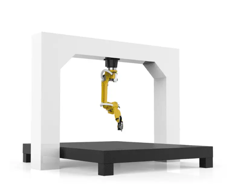
This report details the field implementation and performance evaluation of the Precision CMT Fiber Laser Cobot at a heavy-industrial fabrication facility in Houston, Texas. The facility primarily handles high-volume structural components and pressure vessel bracketry. The objective was to transition a significant portion of Mild Steel welding from traditional Gas Metal Arc Welding (GMAW) to a 1.5kW Fiber Laser system integrated with a collaborative robot (Cobot) arm.
The Texas Gulf Coast environment presents specific challenges for high-precision Laser Technology. Specifically, high ambient humidity and particulate matter in the shop atmosphere necessitated a robust cooling system and pressurized optical housings. This report focuses on the practical synergy between the Fiber Laser Cobot hardware and the metallurgical requirements of A36 and 1018 mild steel grades.
The Synergy of Fiber Laser Cobot and Laser Technology
The core advantage observed during this deployment is the marriage of the 1070nm wavelength provided by Laser Technology and the repeatable pathing of the Fiber Laser Cobot. Manual handheld laser welding, while fast, is prone to inconsistency in travel speed and focal distance, which leads to “undercut” or “burn-through” on thinner mild steel gauges.
Power Density and Beam Profile
In this application, the Fiber Laser Cobot utilized a wobbling head configuration. By oscillating the beam in a circular or “figure-8” pattern, we were able to compensate for slight gaps in the fit-up of Mild Steel welding components. The high power density of the fiber source allows for deep penetration with a fraction of the heat input required by traditional arc welding. This synergy ensures that the heat-affected zone (HAZ) is minimized, preserving the structural integrity of the base metal.
Mild Steel Welding: Technical Observations
While Mild Steel welding is often considered “forgiving” in manual processes, Laser Technology requires a more disciplined approach to metallurgy and joint preparation. Our field tests focused on 10-gauge to 1/4-inch A36 plates.
Metallurgical Impact and HAZ
The narrow, deep fusion profile of the fiber laser creates a very specific cooling rate. In the Texas workshop, where ambient temperatures can reach 105°F, we monitored the interpass temperatures closely. We found that the Fiber Laser Cobot maintained a HAZ roughly 75% smaller than that of a pulsed GMAW setup. This reduction in heat prevented the warping of long 10-gauge panels, which had previously required significant post-weld straightening.
Assist Gas Selection
A critical lesson learned during the first week of deployment was the impact of assist gas on Mild Steel welding. While Nitrogen provides the cleanest finish, the cost in a high-volume Texas shop can be prohibitive. We transitioned to a high-pressure compressed air system (filtered to ISO 8573-1 Class 1.2.1) for the fiber laser. This provided sufficient shielding for the molten pool while significantly lowering the operational cost per foot of weld, without sacrificing the tensile strength of the joints.
Integration Logistics: The Texas Workshop Context
Deploying a Fiber Laser Cobot in an established Texas fab shop requires more than just plugging in the machine. It requires a shift in the “fit-up” culture. Traditional Mild Steel welding allows for gaps of 1/16th or even 1/8th of an inch. Laser Technology is not as lenient.
Joint Preparation and Fit-Up
We implemented new shearing and laser-cutting tolerances for all parts destined for the cobot cell. The Fiber Laser Cobot requires a fit-up gap of less than 10% of the material thickness for autogenous welds. If the gap exceeds this, we found that adding a cold wire feeder to the cobot setup was necessary. The wire feeder integration allowed us to bridge gaps up to 1.5mm while maintaining a travel speed of 40 inches per minute (IPM) on 1/8-inch mild steel.
Safety and Enclosure Requirements
Given the Class 4 nature of Laser Technology, the “open-shop” layout common in many Texas facilities had to be modified. We constructed a light-tight enclosure with interlocking doors. The cobot’s sensors were integrated into the enclosure’s safety circuit. This is a critical field observation: a Fiber Laser Cobot is only “collaborative” in its motion; the laser beam remains a significant ocular hazard. Integration of localized fume extraction was also necessary due to the high-velocity vapor plume generated during the laser-mild steel interaction.
Lessons Learned: Field Notes from the Senior Engineer
1. The “Wobble” Parameter is Non-Negotiable
On Mild Steel welding applications, using a static beam leads to brittle weld centers if the cooling rate is too high. By utilizing the Fiber Laser Cobot‘s ability to modulate the wobble frequency (we found 150Hz to be the sweet spot), we achieved a much smoother bead profile that mimicked the aesthetics of a high-end TIG weld but at 5x the speed.
2. Surface Contamination Management
Texas shops often deal with “mill scale” on hot-rolled mild steel. While Laser Technology can burn through light oils, heavy mill scale causes spatter that can foul the protective lens (cover slide) of the laser head. We moved to a “clean-edge” protocol using mechanical flappers on the weld seam. This reduced lens replacements from twice a day to once a week.
3. Software Pathing vs. Real-World Variance
The Fiber Laser Cobot is only as good as its touch-sensing. We learned that for long seams (over 24 inches) on Mild Steel welding, the thermal expansion of the part during the weld would cause the joint to move. We implemented “mid-path” touch-off points in the cobot programming to recalibrate the tool center point (TCP) every 12 inches. This ensured the laser stayed centered on the root of the joint.
Performance Metrics and ROI
After 90 days of operation in the Texas facility, the data reflects the following:
- Speed Increase: Average travel speed for 3/16-inch fillet welds increased from 12 IPM (Manual GMAW) to 45 IPM (Fiber Laser Cobot).
- Post-Weld Processing: Grinding time was reduced by 90% because the laser process produces zero spatter on Mild Steel welding.
- Consumable Cost: While the initial investment in Laser Technology is high, the elimination of welding wire (in autogenous applications) and the reduction in shielding gas volume resulted in a 30% reduction in consumable cost per part.
Technical Challenges Encountered
The primary technical hurdle was the “Fiber Laser-Induced Plasma” when welding thick-to-thin mild steel transitions. The plasma plume can occasionally interfere with the beam’s focus. We solved this by angling the laser head at a 10-degree lead angle, pushing the plasma away from the incoming beam path. This is a nuance that standard cobot programming often misses but is vital for 24/7 production environments.
Conclusion
The deployment of the Precision CMT Fiber Laser Cobot in this Texas-based application proves that Laser Technology is no longer confined to clean-room environments or high-end aerospace. When applied with a deep understanding of Mild Steel welding dynamics—specifically focusing on joint prep, wobble parameters, and thermal management—the cobot becomes a force multiplier. The synergy between the precision of the fiber source and the flexibility of the cobot arm allows for a level of throughput that traditional arc welding cannot match, provided the engineering team respects the tighter tolerances required by the light-based process.
Future iterations will look into the integration of real-time weld monitoring sensors to further automate the QC process, potentially eliminating the need for manual VT (Visual Testing) on standard structural brackets.
Report Prepared By: Senior Welding Engineer, Site Lead (Texas District)