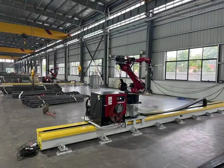
Automatic Girth Seam Welder with Zero-tailing technology for Wind Tower fabrication

In this article
- Efficiency Parameters in Wind Tower Girth Seam Welding
- Robotic MAG Process Control and Deposition Management
- Maintenance Protocols for High-Uptime Environments
- Preventative Maintenance (PM) Schedules
- Torch and Cable Management
- Labor ROI and Economic Analysis
- Quantifying Labor Reductions
- Capital Expenditure vs. Operational Savings
- Strategic Engineering Conclusion
Efficiency Parameters in Wind Tower Girth Seam Welding
In wind tower fabrication, the girth seam represents the most critical structural junction. Traditional submerged arc welding (SAW) has long been the standard, but the transition toward Robotic Welding using high-efficiency MAG (Metal Active Gas) processes is redefining throughput metrics. The core objective of any industrial engineer in this sector is to maximize the duty cycle while minimizing the “tailing” effect—the redundant weld metal at the start and stop points of a circumferential seam.
Zero-tailing technology utilizes advanced sensors and synchronized rotation speeds to ensure that the weld bead overlap is precise. In a standard setup, the overlap often requires manual grinding or secondary machining to meet the rigorous fatigue-life specifications of wind turbine OEMs. By implementing an automated zero-tailing system, the welder adjusts the wire feed speed and voltage in real-time as it closes the 360-degree loop, resulting in a flush transition that eliminates post-process labor.
Robotic MAG Process Control and Deposition Management
The shift to MAG welding in robotic girth systems allows for greater control over the weld pool compared to traditional flux-based systems. Engineers focus on the metal transfer mode—typically pulsed-spray transfer—to maintain arc stability during the long durations required for large-diameter towers.
Optimizing Deposition Rates
High-capacity wind towers require thick-walled sections, often exceeding 50mm. To remain competitive, the robotic welding system must maintain a high deposition rate (kg/h). Using tandem-wire MAG configurations or high-speed single-wire setups, the zero-tailing welder manages the heat input to prevent burn-through while ensuring deep penetration. The synchronization between the rotator (turning rolls) and the welding head is managed via a PLC, ensuring the surface speed remains constant regardless of the tower diameter.
Shielding Gas and Bead Morphology
The choice of shielding gas (typically an Argon/CO2 mix) is optimized to minimize spatter. Spatter reduction is not just an aesthetic concern; in an automated environment, spatter buildup on the gas nozzle leads to turbulence in the gas flow, which causes porosity. Zero-tailing systems often incorporate automated nozzle cleaning stations that the robot visits between seams to ensure consistent gas coverage and bead morphology.
Maintenance Protocols for High-Uptime Environments
From an industrial engineering perspective, the Reliability, Availability, and Maintainability (RAM) of the welding cell are paramount. A robotic girth welder operates in a harsh environment characterized by high ambient heat and metallic dust.
Preventative Maintenance (PM) Schedules
To prevent unscheduled downtime, the maintenance strategy must focus on three primary subsystems:
- Wire Feed Assembly: Rollers must be inspected for wear every 40 hours of arc time. Any slippage in the wire feed results in arc instability, which ruins the zero-tailing precision.
- Contact Tip Life: Using heavy-duty chrome-zirconium contact tips is standard. However, the automated system should track “arc-on” time and prompt a tip change before the orifice becomes oblong (ovality), which causes wire wander.
- Rotator Calibration: The mechanical synchronization between the welding tractor and the vessel rotators must be calibrated monthly. Any drift in the encoder feedback will cause the zero-tailing algorithm to miscalculate the overlap point.
Torch and Cable Management
Robotic girth welders often utilize long umbilical cables. Engineers must monitor the friction within the liners. Increased friction leads to “bird-nesting” at the feeder. The use of low-friction polymer liners and regular compressed air blow-outs of the cable assembly are required to maintain the precision needed for Automatic Girth Seam Welder operations.
Labor ROI and Economic Analysis
The primary driver for adopting automatic girth seam welders with zero-tailing capability is the drastic reduction in man-hours per tower. In a manual or semi-automated environment, the girth seam requires a skilled welder, a helper, and a dedicated grinder.
Quantifying Labor Reductions
With a zero-tailing robotic system, the labor requirement shifts from “welding” to “monitoring.” One technician can often oversee two welding stations. The ROI is calculated by looking at:
- Direct Labor Savings: Reduction of 60-70% in manual welding hours.
- Elimination of Secondary Operations: Zero-tailing removes the need for 1-2 hours of grinding and polishing per seam.
- Rework Mitigation: Human error in the overlap area is a frequent cause of NDT (Non-Destructive Testing) failure. Robotic precision reduces the defect rate to under 1%, saving thousands in gouging and repair costs.
Capital Expenditure vs. Operational Savings
While the initial investment in a zero-tailing technology system is higher than a standard tractor welder, the payback period is typically achieved within 12 to 18 months in high-volume wind tower facilities. The consistency of the robotic MAG process ensures that the production schedule is predictable, allowing for better upstream and downstream logistics management.
Strategic Engineering Conclusion
The integration of automatic girth seam welders with Zero-tailing technology represents a critical leap in wind tower fabrication efficiency. By focusing on the MAG process and rigorous robotic maintenance, manufacturers can achieve a level of consistency that manual labor cannot match. The reduction in “tailing” waste and the optimization of deposition rates directly contribute to a lower cost-per-megawatt for wind energy infrastructure. For the industrial engineer, the focus remains on the data-driven optimization of these systems to ensure maximum equipment effectiveness (OEE) and long-term structural integrity of the fabricated towers.