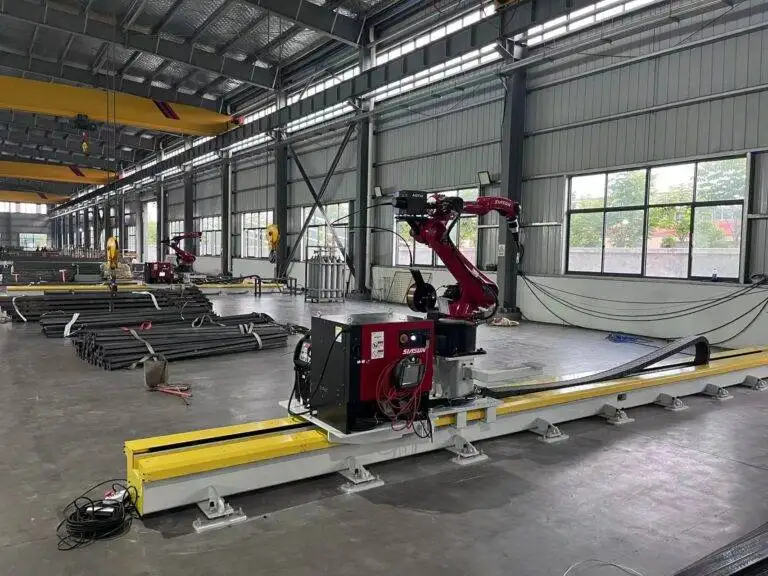
Automatic Girth Seam Welder with Zero-tailing technology for Shipbuilding

In this article
The Engineering Logic of Zero-Tailing in Maritime Welding
In the heavy industry of shipbuilding, the girth seam represents one of the most critical structural junctions. Traditionally, circumferential welding of large hull sections or storage tanks required significant manual intervention, leading to “tailing”—unwelded gaps or stop-start defects at the beginning and end of a track. The introduction of zero-tailing technology addresses this specific bottleneck. By utilizing specialized carriage designs and offset torch mounts, these robotic systems allow the welding arc to reach the absolute edge of a plate or the junction of a bulkhead without the mechanical interference typically caused by the tractor’s drive wheels.
From an industrial engineering perspective, the objective is to maximize the effective welding length per setup. Zero-tailing mechanisms utilize a precision-machined guide rail and a cantilevered arm that moves the MAG Robotic Welding torch ahead of the tractor’s frame. This allows for a continuous bead that covers the entire circumference or longitudinal run, minimizing the need for manual “tie-ins.” By eliminating these manual patches, shipyards reduce the probability of volumetric defects such as slag inclusions or cold laps, which are common at the start-stop points of a weld cycle.
Technical Specifications of the MAG Robotic Carriage
The core of the Automatic Girth Seam Welder is the Metal Active Gas (MAG) process. Unlike Flux-Cored Arc Welding (FCAW) which produces significant slag, MAG welding provides a cleaner profile and higher deposition efficiency, particularly when used with solid wires and argon-CO2 shielding gas blends. The robotic carriage is engineered to maintain a constant contact-tip-to-work distance (CTWD), which is vital for maintaining arc stability across the varying curvatures of a ship’s hull.
The system integrates an advanced wire feed control loop. Modern units employ high-torque motors with encoder feedback to ensure that the wire speed remains synchronized with the carriage travel speed. If the carriage encounters a slight resistance on the track, the controller compensates to prevent fluctuations in the weld bead geometry. This level of precision is unattainable by manual operators over the course of an eight-hour shift, where fatigue inevitably leads to variations in travel speed and torch angle.
Overcoming Traditional Girth Seam Constraints
Girth welding presents unique challenges, specifically regarding gravity’s effect on the molten weld pool. As the welder moves around the circumference, the weld position shifts from flat to vertical and potentially overhead. Automatic systems counteract this through oscillation control. The robotic head can be programmed to perform a “weave” pattern, where the width, frequency, and dwell time at the edges are adjusted in real-time. This ensures proper sidewall fusion and prevents the weld metal from sagging, maintaining a uniform throat thickness throughout the seam.
Maintenance Protocols for High-Duty Cycle Systems
To realize the long-term benefits of an automatic welder, a shipyard must implement a proactive maintenance framework. Because these machines operate at duty cycles often exceeding 80%, the thermal load on the internal components is substantial. Maintenance is categorized into consumable management and mechanical calibration.
The primary consumables in MAG robotic welding are the contact tips and the gas nozzles. In a high-volume environment, contact tips experience “keyholing,” where the wire erodes the copper orifice, leading to arc wander. Engineers must establish a replacement schedule based on the mass of wire consumed rather than elapsed time. Furthermore, the wire liners—the conduits that guide the electrode from the spool to the torch—must be cleaned with compressed air periodically to remove copper flaking and dust, which can cause erratic feeding and “bird-nesting” at the drive rolls.
Managing Drive Systems and Track Integrity
The mechanical drive system requires weekly inspections. In a shipyard, ambient contaminants such as metallic dust and grinding grit can infiltrate the carriage gears. Industrial engineers should mandate the use of sealed bearings and ensure that the drive tracks are leveled and free of obstructions. Any deviation in the track alignment will manifest as a defect in the weld seam, necessitating expensive rework. A monthly calibration of the carriage’s travel speed using a tachometer is recommended to ensure the programmed heat input remains within the parameters specified by the Welding Procedure Specification (WPS).
Economic Justification: Labor ROI and Throughput Metrics
The transition from manual girth welding to an automated zero-tailing system is a capital-intensive decision that requires a robust shipyard labor ROI analysis. The primary driver of ROI in this context is the “Arc-on Time” ratio. A manual welder typically achieves an arc-on time of 20% to 30% due to the need for repositioning, breaks, and weld cleaning. An automatic girth welder can maintain an arc-on time of 75% or higher.
When calculating ROI, engineers must factor in the reduction of “man-hours per meter of weld.” For example, if a manual process requires 10 hours to complete a specific circumference including setup and grinding, the automated system might reduce this to 2.5 hours. Furthermore, the zero-tailing feature eliminates the 15-20 minutes typically spent by a secondary operator to manually fill the “tail” sections left by standard tractors. Over a project involving several kilometers of girth seams, these minutes aggregate into hundreds of saved labor hours.
Reducing the Cost of Quality
Rework is the most significant “hidden” cost in shipbuilding. X-ray and ultrasonic testing (UT) of girth seams are standard. Manual welding often results in a 5% to 8% repair rate due to human error. Automatic MAG systems, once dialed in, can reduce repair rates to less than 1%. The cost of a single weld repair involves gouging out the defect, re-welding, and re-testing—a process that is often five times more expensive than the original weld. By minimizing these occurrences, the automatic welder pays for its own depreciation through the avoidance of quality-related losses.
Capital Expenditure vs. Operational Efficiency
While the initial CapEx for a zero-tailing robotic welder is significantly higher than manual power sources, the Opex is lower. The reduction in shielding gas waste and electrode stub-loss, combined with the decreased reliance on highly skilled (and high-cost) manual welders, shifts the break-even point to within the first 12 to 18 months of operation for most mid-to-large shipyards. Additionally, the ability to train lower-skilled operators to monitor the machine—rather than needing veteran welders to execute the weld—allows for better labor allocation across the facility.
Conclusion on Future-Proofing Shipyard Operations
The implementation of automatic girth seam welders with Zero-tailing technology is no longer an optional upgrade but a necessity for shipyards aiming to remain competitive in a global market. The precision of the MAG process, combined with a rigorous maintenance schedule and the clear financial advantages of robotic automation, provides a stable foundation for increasing throughput. By focusing on the elimination of “tailing” and the maximization of arc-on time, industrial engineers can ensure that their production lines operate with the highest possible efficiency and the lowest possible defect rate.