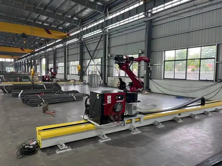
Automatic Girth Seam Welder with 3D Vision positioning for Shipbuilding

In this article
- Engineering the Transition to Automated Girth Welding
- The Role of 3D Vision Positioning in Adaptive Welding
- Spatial Mapping and Real-Time Feedback Loops
- Compensating for Thermal Distortion
- Optimizing the Robotic MAG Process
- Deposition Rates and Throughput Analysis
- Wire Feed Consistency and Spatter Control
- Quantifying Labor ROI and Economic Viability
- Direct Labor Displacement vs. Skill Reallocation
- The Cost of Weld Quality
- Maintenance Protocols for Robotic Uptime
- Conclusion: The Competitive Edge in Shipbuilding
Engineering the Transition to Automated Girth Welding
In the heavy industrial sector of shipbuilding, the girth seam—the circumferential joint connecting cylindrical hull sections or tubular pillars—represents a critical path in production scheduling. Traditionally, these seams were handled by teams of manual welders operating in arduous conditions. However, the volatility of manual weld quality and the increasing scarcity of certified high-pressure welders have necessitated a shift toward the Automatic Girth Seam Welder. From an industrial engineering perspective, the goal is not merely to replace the human element but to stabilize the process cycle time and maximize the duty cycle of the welding power source.
Robotic systems designed for Shipbuilding must account for the massive scale of workpieces. Unlike small-scale automotive robotics, a girth seam welder for ship sections must traverse tracks or internal carriages, maintaining precision over distances exceeding 30 meters. The application of Metal Active Gas (MAG) welding in these systems allows for high-speed deposition, but its success is entirely dependent on the system’s ability to navigate the inherent imperfections of large-scale steel fabrication.
The Role of 3D Vision Positioning in Adaptive Welding
One of the primary roadblocks to automation in shipyards is the lack of perfect fit-up. Large steel plates, even when rolled with precision, exhibit deviations in root opening, groove angle, and alignment. Traditional “teach-and-repeat” robotics fail here because the weld path is never identical twice. This is where 3D Vision Positioning becomes the central nervous system of the welding unit.
Spatial Mapping and Real-Time Feedback Loops
The 3D vision system utilizes structured light or stereoscopic sensors to scan the joint geometry millimeters ahead of the welding arc. The software generates a point cloud that identifies the exact center of the groove and measures the volume of the gap. For an industrial engineer, this data is vital for “Adaptive Fill” parameters. If the 3D sensor detects a wider gap, the robot’s controller automatically adjusts the travel speed, wire feed speed, or weave amplitude to ensure the weld bead maintains structural integrity without burn-through.
Compensating for Thermal Distortion
Shipbuilding involves thick-plate welding where heat input is substantial. As the MAG process progresses around the circumference, the steel expands and contracts, causing the seam to “creep” or “close up.” A 3D vision-enabled system tracks these dynamic changes in real-time, adjusting the torch orientation (work angle and travel angle) to maintain the optimal contact-tip-to-work distance (CTWD). This level of precision virtually eliminates the “stop-and-grind” cycles common in manual operations.
Optimizing the Robotic MAG Process
The choice of Metal Active Gas (MAG) welding as the primary process for girth seams is driven by its high deposition efficiency and ability to operate in various positions. By utilizing a shielding gas mix—typically Argon and CO2—the process provides deep penetration and a stable arc, which is essential for the heavy gauges used in hull construction.
Deposition Rates and Throughput Analysis
In a manual environment, a welder’s arc-on time (duty cycle) rarely exceeds 30% due to fatigue, repositioning, and helmet-down time. An automated girth welder operates at a duty cycle approaching 80% to 90%. By utilizing tandem-wire MAG configurations or high-efficiency wave-form control, deposition rates can be increased from 3kg/hr (manual) to over 12kg/hr (robotic). This four-fold increase in metal deposition directly translates to faster section completion and reduced shipyard lead times.
Wire Feed Consistency and Spatter Control
Robotic MAG systems utilize high-torque wire feeders and specialized liners to ensure that the electrode wire is delivered without kinking or slippage. Controlled short-circuit or pulsed-spray transfer modes are programmed into the robot’s power source to minimize spatter. Reducing spatter is not just an aesthetic concern; it significantly reduces the post-weld labor required for cleaning and surface preparation before NDT (Non-Destructive Testing) and painting.
Quantifying Labor ROI and Economic Viability
The capital expenditure for an automated girth seam welder is significant, yet the Labor ROI is often realized within 18 to 24 months in high-volume shipyards. This return is calculated through three primary vectors: labor displacement, rework reduction, and consumable efficiency.
Direct Labor Displacement vs. Skill Reallocation
Automated systems allow a single operator to oversee two or even three welding carriages simultaneously. The role of the “welder” shifts to that of a “system technician.” This reallocates high-cost human capital to complex tasks that cannot be automated, such as intricate outfitting or repair work, while the robot handles the repetitive, high-volume girth seams. In a three-shift shipyard operation, the savings on hourly wages, benefits, and insurance for a dozen manual welders quickly offsets the cost of the robotic hardware.
The Cost of Weld Quality
In shipbuilding, a single failed radiographic test (RT) on a girth seam can cost thousands of dollars in gouging, re-welding, and delay penalties. Automated systems with 3D vision produce a level of consistency that manual welders cannot match over a 10-hour shift. By lowering the defect rate from a typical 5-8% (manual) to less than 1% (robotic), the shipyard saves an immense amount of “hidden” labor costs associated with quality control failures.
Maintenance Protocols for Robotic Uptime
To sustain the ROI, the industrial engineer must implement a rigorous preventative maintenance (PM) schedule. Unlike manual welding machines, robotic cells have sensitive mechanical and optical components that require specific care.
Torch and Consumable Management
The MAG torch is the most frequent point of failure. Automated reaming stations should be integrated into the system to periodically clean the nozzle of spatter buildup. Contact tips must be replaced on a schedule based on “wire-meters-consumed” rather than waiting for failure. This prevents arc instability that could lead to porosity or lack of fusion.
3D Vision Sensor Calibration
The optical sensors are the “eyes” of the system and are susceptible to the harsh environment of a shipyard. Maintenance must include daily cleaning of the protective glass and weekly calibration checks to ensure the 3D point cloud remains aligned with the robot’s TCP (Tool Center Point). Any misalignment here renders the adaptive welding capabilities useless.
Drive System and Track Integrity
Because the girth welder moves along the circumference of the ship section, the rail or track system must be inspected for debris or magnetic interference. A stumble in the drive motor due to a dirty track will cause a blemish in the weld bead, potentially necessitating a repair. Lubrication of the gears and verification of the encoder feedback loops are essential monthly tasks.
Conclusion: The Competitive Edge in Shipbuilding
The integration of an Automatic Girth Seam Welder with 3D Vision positioning is no longer a luxury for modern shipyards; it is a competitive necessity. By mastering the Metal Active Gas (MAG) welding process through automation, facilities can overcome the dual challenges of labor shortages and tightening quality standards. The Labor ROI is supported by undeniable data: higher deposition rates, near-zero rework, and the ability to operate continuously across multiple shifts. For the industrial engineer, the focus remains on the synthesis of robust hardware, intelligent sensing, and disciplined maintenance to ensure that the shipyard of tomorrow remains productive and profitable.