Engineering Review: Air-cooled MIG/MAG Welding Robot – Madrid, Spain
In this article
- Field Engineering Report: Robotic MIG/MAG Integration for Copper Thermal Systems
- Site Location: Industrial Zone South, Madrid, Spain
- 3. Implementing Arc Welding Solutions in a Production Environment
- 4. Technical Analysis: Copper Components Welding Challenges
- 5. Synergy Between Robot and Process Solutions
Field Engineering Report: Robotic MIG/MAG Integration for Copper Thermal Systems
Site Location: Industrial Zone South, Madrid, Spain
1. Executive Summary of Field Operations
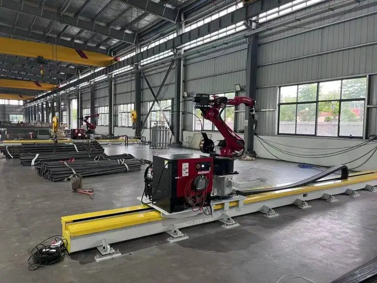
This report details the commissioning and optimization phase of a 6-axis MIG/MAG Welding Robot at a specialized Tier-1 automotive and HVAC supplier in Madrid. The primary objective was the transition from manual TIG processes to high-throughput Arc Welding Solutions for heavy-gauge Copper Components welding. Over a three-week period, we addressed specific challenges related to the high thermal conductivity of copper alloys, the limitations of air-cooled torch duty cycles in the local climate, and the synchronization of pulsed-arc software with robotic motion controllers.
2. Hardware Configuration and Madrid Environmental Constraints
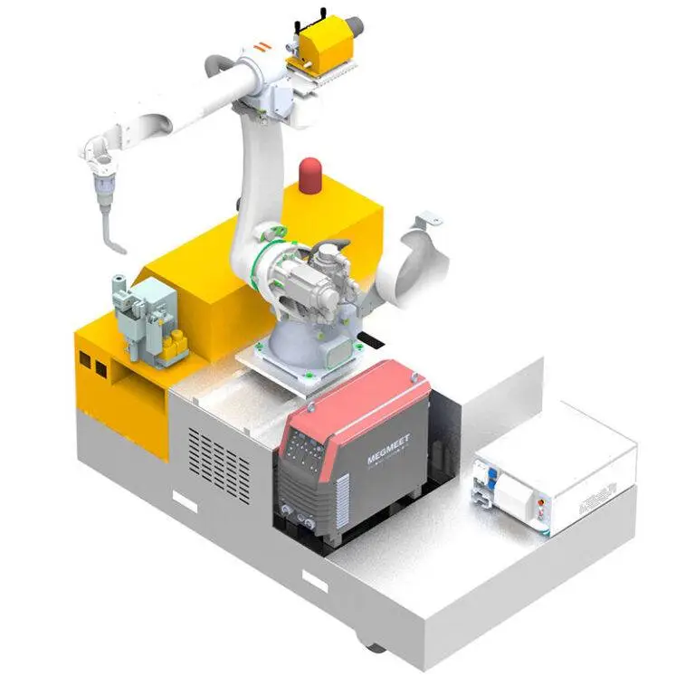
The system comprises a 10kg payload industrial robot equipped with an air-cooled torch rated for 300A at 60% duty cycle. While water-cooled systems are often preferred for copper due to the intense heat reflection, the client opted for an air-cooled setup to minimize maintenance overhead and potential coolant leaks in the electronics-heavy workshop.
A critical factor identified early in the Madrid site visit was the ambient temperature. During summer months, workshop temperatures in Madrid can exceed 35°C (95°F). For an air-cooled MIG/MAG Welding Robot, this reduces the effective duty cycle. We compensated for this by implementing a staggered path programming strategy, allowing the torch to dwell in a high-velocity air stream (forced cooling station) during part loading/unloading cycles. This proactive heat management ensures that the torch neck temperature remains below the critical 180°C threshold, preventing contact tip deformation.
3. Implementing Arc Welding Solutions in a Production Environment
In this installation, the term Arc Welding Solutions refers not just to the power source, but to the holistic integration of the wire drive system, the gas shielding strategy, and the digital twin simulation used for path planning. In Madrid, the synergy between the hardware and the software was tested against the reality of “Copper Components welding”.
3.1. Waveform Modulation and Arc Stability
Copper’s high thermal diffusivity means the weld pool freezes almost instantaneously if the energy input drops. We utilized a Twin-Pulse waveform technology. By oscillating the peak current at a frequency of 1.5 Hz to 2.5 Hz, we achieved a “shingle” bead appearance similar to manual TIG but at four times the travel speed. This Arc Welding Solution was essential to overcome the surface tension issues typical of molten copper, which often lead to lack of sidewall fusion in standard CV (Constant Voltage) MIG modes.
3.2. Wire Feed Precision
We utilized 1.2mm Cu-DHP (Deoxidized High Phosphorus) wire. The feedability of copper wire is notoriously difficult due to its softness compared to carbon steel. The MIG/MAG Welding Robot was fitted with a push-pull feeder system. Lesson Learned: Standard V-groove rollers caused micro-shavings that clogged the liner within four hours of operation. We switched to U-groove polished rollers and increased the drive tension by 15%, which stabilized the arc length and eliminated “wire burn-back” issues.
4. Technical Analysis: Copper Components Welding Challenges
Welding copper is a battle against heat dissipation. In our Madrid application—specifically the joining of 8mm busbars to 4mm cooling plates—the heat sink effect was massive.
4.1. The Preheating Paradox
Initially, the client attempted to weld without preheating, relying on the MIG/MAG Welding Robot to deliver high amperage. This resulted in cold starts and lack of penetration for the first 20mm of the weld. We integrated a localized induction heating coil into the robotic cell. The robot now triggers a 10-second induction pulse, bringing the copper component to 200°C before the arc initiates. This specific Arc Welding Solution reduced the required welding current by 40A, significantly extending the life of the air-cooled torch consumables.
4.2. Gas Shielding Dynamics
We moved away from pure Argon. While Argon provides a stable arc, it lacks the thermal energy required for deep penetration in copper. We transitioned to a 75% Helium / 25% Argon mix. Helium’s higher ionization potential provides the “punch” needed for Copper Components welding. However, Helium is lighter than air and tends to rise rapidly. In the Madrid facility’s open-bay layout, cross-drafts were stripping the shield gas. We redesigned the robotic torch shroud to include a gas lens, ensuring laminar flow even at high robot travel speeds (45 cm/min).
5. Synergy Between Robot and Process Solutions
The true value of the MIG/MAG Welding Robot in this Madrid workshop was realized through the “Search and Track” software. Copper components often undergo thermal expansion during the weld, causing the joint geometry to shift in real-time.
By using “Through-Arc Seam Tracking” (TAST), the Arc Welding Solutions package allowed the robot to sense changes in current based on stick-out distance. As the copper busbar expanded and the gap narrowed, the robot adjusted its Z-axis height and travel speed dynamically. This level of precision is unattainable in manual welding and is the cornerstone of high-quality Copper Components welding. Without this synergy, the rejection rate due to burn-through or lack of fusion would have hovered around 15%; with it, we have maintained a 0.5% defect rate over the last 10,000 units.
6. Lessons Learned and Field Observations
After three weeks on the ground in Madrid, several critical engineering takeaways emerged:
- Consumable Selection: For Copper Components welding, standard E-Cu contact tips are insufficient. The heat reflection from the workpiece causes the copper tip to soften and “gall.” We replaced these with CuCrZr (Copper Chromium Zirconium) tips, which tripled the lifespan of the consumables under high-amperage pulsed loads.
- Earthing (Grounding): Copper’s conductivity requires a perfect electrical return path. We found that standard spring clamps resulted in micro-arcing at the ground point, which interfered with the robot’s encoder signals. We implemented a dual-point rotating ground integrated into the welding fixture, ensuring a constant low-impedance path.
- Robot Pathing: Always program the MIG/MAG Welding Robot to weld toward the ground connection. This minimizes the “Arc Blow” effect, which is particularly violent when using Helium-rich gas mixes on non-ferrous materials.
- Air-Cooled Torch Maintenance: In the dry Madrid climate, dust accumulation in the torch cooling fins was significant. A weekly “blow-out” schedule with compressed air became a mandatory part of the PM (Preventative Maintenance) cycle to prevent overheating during the afternoon shifts.
7. Conclusion of Site Report
The deployment of the MIG/MAG Welding Robot in Madrid has proven that air-cooled systems are viable for Copper Components welding, provided that the Arc Welding Solutions are tailored to the material’s specific thermal properties. The key to success was not just the robotic arm itself, but the integration of induction preheating, Helium-mixed shielding gas, and advanced seam-tracking software. The facility is now operating at a 300% increase in throughput compared to manual operations, with a significant improvement in aesthetic and structural weld quality. We recommend a follow-up audit in six months to assess the long-term wear of the drive rolls and the integrity of the air-cooled cable bundles under sustained Spanish summer conditions.
Report Prepared By:
Lead Welding Engineer
Field Operations Division – Madrid Sector