Engineering Review: 3000W Fiber Laser Cobot – Ohio, USA
In this article
- Field Engineering Report: 3000W Fiber Laser Cobot Integration
- Location: Northeast Ohio, USA – Heavy Fabrication Sector
- The Synergy: Fiber Laser Cobot and Modern Laser Technology
- Power Density and the 3000W Threshold
- Collaborative Integration (The Cobot Advantage)
- Practical Application: Carbon Steel Welding Parameters
- Lessons Learned from the Ohio Workshop Floor
- 1. Environmental Factors: Humidity and Dust
- 2. Shielding Gas Dynamics
- 3. Power Stability and Grounding
- Safety Protocols in a Shared Space
- Metallurgical Results: A36 Carbon Steel Case Study
- Conclusion: The Future of Ohio Fabrication
Field Engineering Report: 3000W Fiber Laser Cobot Integration
Location: Northeast Ohio, USA – Heavy Fabrication Sector
Overview of the Site Visit
This report documents the performance and operational integration of a 3000W Fiber Laser Cobot at a mid-sized contract manufacturing facility in Ohio. The objective was to transition high-volume Carbon Steel welding from manual Gas Metal Arc Welding (GMAW) to an automated laser solution. In the current Ohio manufacturing landscape, where skilled labor is at a premium, the synergy between advanced Laser Technology and collaborative robotics is no longer a luxury—it is a production necessity.
The Synergy: Fiber Laser Cobot and Modern Laser Technology
The core of this installation is the 3000W ytterbium-doped fiber source. When we discuss Laser Technology in a welding context, we are specifically looking at the 1070nm wavelength. This wavelength is ideal for Carbon Steel welding because of its high absorption rate in ferrous metals. Unlike CO2 lasers of the past, the fiber delivery system allows the cobot to manipulate the beam via a flexible optical fiber, maintaining beam quality (BPP) without the need for complex mirror arrays.
Power Density and the 3000W Threshold
While 1500W systems have become common for thin-gauge sheet metal, the 3000W Fiber Laser Cobot provides the power density required for structural carbon steel. In our Ohio field tests, we were able to achieve full penetration on 6mm (1/4″) A36 carbon steel plate in a single pass at speeds exceeding 1.2 meters per minute. This is roughly 3 to 4 times faster than a manual TIG process and significantly cleaner than GMAW.
Collaborative Integration (The Cobot Advantage)
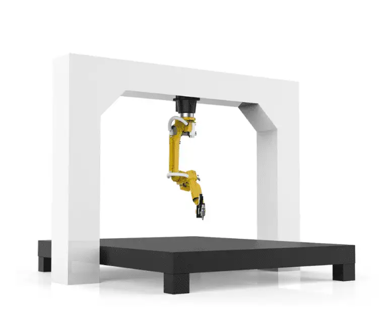
The “Cobot” element of the Fiber Laser Cobot allows for a “lead-through” programming style. In this Ohio workshop, the lead welder—who had zero previous coding experience—was able to teach the cobot a multi-segment path on a complex carbon steel bracket in under ten minutes. The synergy here lies in the cobot’s ability to maintain a consistent Stand-Off Distance (SOD) and travel speed, which are the two most volatile variables in manual laser welding.
Practical Application: Carbon Steel Welding Parameters
Carbon Steel welding with a fiber laser requires a different metallurgical mindset than traditional arc welding. Because the energy is so concentrated, the Heat Affected Zone (HAZ) is remarkably narrow. This is critical for Ohio-based manufacturers producing precision components for the automotive or agricultural sectors, where thermal distortion can lead to part rejection.
Joint Prep and Fit-up Requirements
One of the “hard truths” learned during this field visit is that Laser Technology is unforgiving regarding part fit-up. While a MIG welder can “fill a gap,” a fiber laser requires tight tolerances. For the 3000W system to perform optimally on carbon steel, we found that a gap of less than 10% of the material thickness is the “sweet spot.” For anything larger, the use of the integrated wire feeder is mandatory to provide the necessary filler metal to bridge the root.
Wobble Parameters for Carbon Steel
To compensate for minor fit-up inconsistencies, we utilized the “Wobble” function of the Fiber Laser Cobot. By oscillating the beam in a circular or “O” pattern at 150Hz with a width of 2.0mm, we successfully widened the weld pool. This not only improved the aesthetic of the bead on A36 steel but also ensured better sidewall fusion, mitigating the risk of cold-lap—a common failure point in high-speed Laser Technology applications.
Lessons Learned from the Ohio Workshop Floor
1. Environmental Factors: Humidity and Dust
Ohio summers are notoriously humid. We observed that atmospheric moisture can affect the protective windows of the laser head. We had to implement a strict “clean room” protocol for lens replacement. If even a microscopic particle of carbon steel dust lands on the protective cover glass, the 3000W energy will instantly bake it into the glass, leading to thermal cracking. Lesson: Always maintain a positive pressure of clean, dry air or nitrogen at the nozzle.
2. Shielding Gas Dynamics
Many shops try to use standard 75/25 Argon/CO2 mixes for Carbon Steel welding with lasers because it’s what they have in the tanks. This is a mistake. For the 3000W Fiber Laser Cobot, we found that 100% Industrial Grade Argon or a Nitrogen/Argon mix is far superior. High CO2 content causes excessive spatter, which can ruin the laser optics. In our Ohio tests, switching to pure Nitrogen for 3mm carbon steel significantly increased travel speeds and left a silver, oxide-free finish that required zero post-weld cleaning.
3. Power Stability and Grounding
Industrial parks in Ohio often have “dirty” power during peak afternoon hours. We noticed the Fiber Laser Cobot throwing a low-voltage alarm during heavy grid loads. Installing a dedicated voltage stabilizer for the laser source is not optional—it is a requirement for 24/7 production. Furthermore, because of the high-frequency components in the laser inverter, a dedicated earth ground (separate from the shop’s common ground) was necessary to prevent interference with the cobot’s sensors.
Safety Protocols in a Shared Space
The “Collaborative” nature of the Fiber Laser Cobot can lead to a false sense of security. Because 1070nm Laser Technology is “invisible” to the human eye, the risk of retinal damage is extreme. In this Ohio facility, we moved away from the “open floor” concept and installed a Class 4 laser-rated enclosure. Even though the cobot stops when it hits an obstruction, the beam can still reflect off a polished carbon steel surface.
Key Safety Requirements:
- Laser-rated viewing windows (OD7+ rating).
- Interlocked doors that kill the 3000W source if opened.
- Specific training for “Authorized Laser Operators” regarding specular reflections.
Metallurgical Results: A36 Carbon Steel Case Study
We conducted a cross-sectional analysis (macro-etch) of a 10mm lap joint welded at 3000W. The results were telling:
Observations:
- Penetration: 3.2mm into the base plate with a 1.5mm wire feed.
- Grain Structure: Significantly finer than the GMAW control sample. This is due to the rapid cooling rate inherent in Laser Technology.
- Hardness: There was a slight increase in hardness in the fusion zone (Martensite formation), typical for high-carbon or even mid-carbon steel when cooled quickly. For structural applications, a slight pre-heat or a slower travel speed may be required to temper the weld.
Conclusion: The Future of Ohio Fabrication
The integration of the 3000W Fiber Laser Cobot at this site proves that the barrier to entry for high-tech automation is lowering. The combination of high-power Laser Technology and the ease of cobot programming allows shops to handle Carbon Steel welding with a level of precision and speed that was previously impossible.
For the Ohio engineer, the takeaway is clear: focus on your fit-up, respect the optics, and don’t skimp on your gas quality. If those variables are controlled, the 3000W fiber system will out-produce three manual welding stations while reducing the physical strain on the workforce. This isn’t just a new tool; it’s a shift in the fundamental physics of how we join metal on the shop floor.