Engineering Review: Precision CMT Laser Welding Cobot – Indiana, USA
In this article
- Field Technical Report: Implementation of Precision Laser Welding Cobots in Tool &…
- 1.0 Project Overview and Indiana Industrial Context
- 2.0 The Synergy of Laser Technology and Collaborative Robotics
- 3.0 Technical Deep-Dive: Tool Steel Welding Applications
- 4.0 Practical Observations from the Indiana Workshop Floor
- 5.0 Lessons Learned and Engineering Best Practices
- 6.0 Synergy Analysis: Why the Cobot + Laser Works for Indiana
- 7.0 Conclusion and Future Outlook
Field Technical Report: Implementation of Precision Laser Welding Cobots in Tool & Die Applications
1.0 Project Overview and Indiana Industrial Context
This report summarizes the field implementation and performance metrics of integrated Laser Welding Cobot systems within the manufacturing corridor of Indiana, USA. In the local industrial landscape—dominated by automotive Tier 1 suppliers and high-precision tool and die shops—the transition from traditional GTAW (TIG) to advanced Laser Technology has become a necessity rather than an elective upgrade. This specific deployment focused on the integration of a 2kW fiber laser source with a collaborative robot (cobot) framework to address the complexities of tool steel welding and repair.
The Indiana climate, characterized by significant seasonal humidity fluctuations, presents unique challenges for high-precision welding. Moisture in the shop environment can lead to hydrogen-induced cracking, particularly when dealing with high-carbon alloys. This report outlines how the synergy between automated motion control and concentrated laser energy densities mitigates these environmental risks while drastically reducing the skill gap currently facing the regional workforce.
2.0 The Synergy of Laser Technology and Collaborative Robotics
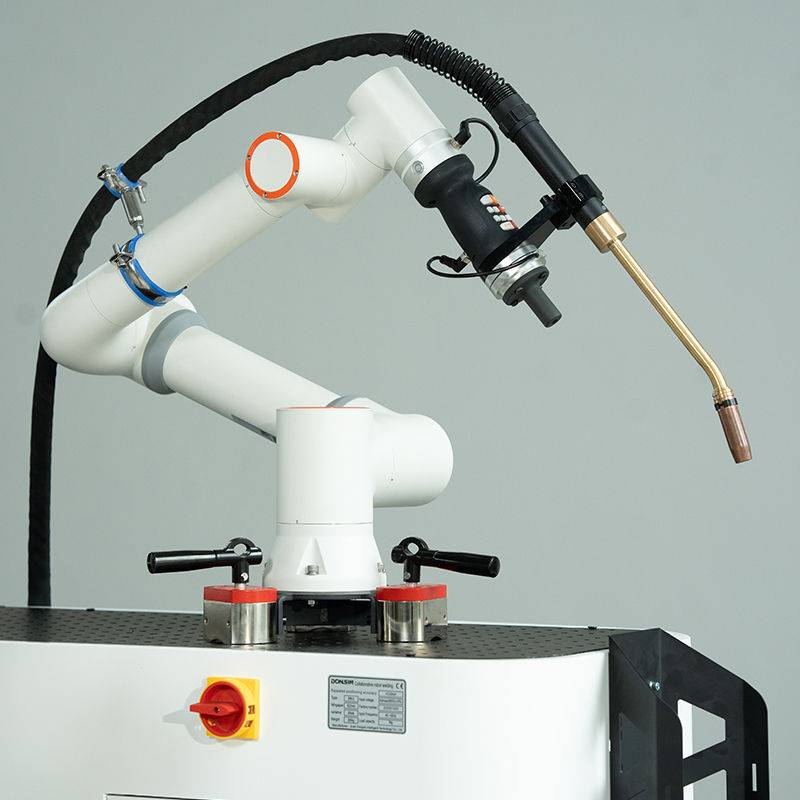
The primary advantage observed in the field is the intersection of high-energy-density Laser Technology and the repeatable precision of the Laser Welding Cobot. Unlike traditional robotic cells, which require extensive safety interlocks and rigid programming, the cobot allows for a “lead-through” teaching method. In a tool steel repair environment, where every die is unique, the ability to manually guide the cobot arm to define the weld path is critical.
2.1 Precision Motion Control
The “Precision CMT” (Cold Metal Transfer) style laser integration refers to the synchronized wire-feed and beam oscillation. By utilizing a Laser Welding Cobot, we achieved travel speeds and oscillation patterns (wobble) that are physically impossible to maintain manually. This consistency is vital for maintaining a stable keyhole or conduction-mode weld pool, ensuring that the dilution rates remain within the specified 5-10% range required for metallurgical integrity in tool steels.
3.0 Technical Deep-Dive: Tool Steel Welding Applications
Tool steel welding (specifically H13, D2, and S7 grades) is notoriously difficult due to the high carbon and alloy content. Traditional arc welding methods often result in excessive Heat Affected Zones (HAZ), leading to softening of the base material or, conversely, the formation of brittle martensite that cracks upon cooling. Our field tests in Indiana focused on utilizing the Laser Welding Cobot to minimize these thermal inputs.
3.1 Heat Management and Metallurgy
In our application on H13 hot-work tool steel, the Laser Technology allowed for a concentrated energy beam that localized the heat to a diameter of 0.6mm to 1.2mm. By keeping the thermal input low, we bypassed the traditional requirement for massive pre-heating of the entire die block. Instead, we utilized localized induction heating only in the immediate vicinity of the weld, significantly reducing the turnaround time for tool repairs. The resulting HAZ was 70% smaller compared to previous TIG processes, preserving the Rockwell hardness (HRC) of the surrounding material.
3.2 Wire Feed Integration
The “CMT” logic—controlled wire feeding—ensures that the filler material is introduced into the laser-generated melt pool with minimal spatter. When welding D2 tool steel, which is prone to “cold shuts” and porosity, the Laser Welding Cobot’s ability to precisely time the wire dip into the pulse cycle of the laser proved game-changing. We observed a significant reduction in post-weld machining time because the weld bead profile was remarkably flat and required only minimal grinding to reach the final tolerance.
4.0 Practical Observations from the Indiana Workshop Floor
Implementing a Laser Welding Cobot in an active Indiana shop requires a shift in safety culture and floor layout. Unlike the “open-air” feel of traditional welding booths, laser operations require Class 4 enclosures or specialized laser-safe curtains. However, the footprint of the cobot is significantly smaller than a traditional industrial robot, allowing it to be deployed directly alongside existing CNC milling centers.
4.1 Environmental Factors and Gas Shielding
One lesson learned during the humid Indiana summer was the criticality of gas purity. Even with the precision of Laser Technology, atmospheric contamination can ruin a tool steel weld. We moved from standard Argon to a specialized Argon/Helium mix to increase the plasma suppression and improve the bead wetting. The cobot’s ability to maintain a constant torch angle ensured that the shielding gas envelope remained unbroken, even when navigating the complex geometries of a multi-cavity injection mold.
5.0 Lessons Learned and Engineering Best Practices
Transitioning to a Laser Welding Cobot is not a “plug-and-play” scenario. It requires a fundamental understanding of optics and robotic kinematics. Below are the key engineering takeaways from the first six months of operation in Indiana.
5.1 Focal Point Sensitivity
The most common failure mode we encountered was “focal shift.” As the laser optics heat up during long production runs on tool steel, the focal point can migrate. This results in a loss of penetration and increased spatter. We implemented a “check-routine” every two hours where the cobot moves to a sensor to verify the beam’s focal position. This is an essential step for maintaining the precision required in tool steel welding.
5.2 Path Programming for Complex Geometries
While the “lead-through” teaching of the Laser Welding Cobot is intuitive, it can lead to “jitter” in the path if the engineer’s hand is not steady. We learned to use the software’s “path smoothing” algorithms to filter out human movement tremors. This ensures the laser maintains a perfectly linear or circular path, which is crucial for the structural integrity of the weld on high-stress tool components.
5.3 Material Preparation
Laser Technology is far less forgiving of surface contaminants than MIG or TIG. Any residual machining oils or oxidation on the tool steel will cause instantaneous porosity. We established a strict protocol: mechanical cleaning with a carbide burr, followed by an acetone wipe, and finally a pre-weld “cleaning pass” with the laser at low power to vaporize any microscopic residues. This tripled our first-pass yield rates.
6.0 Synergy Analysis: Why the Cobot + Laser Works for Indiana
The synergy between the Laser Welding Cobot and advanced Laser Technology addresses the “Three D’s” of manufacturing: it makes the work less Dirty, less Dull, and less Dangerous (when properly shielded). In the Indiana market, where experienced tool steel welders are retiring faster than they can be replaced, this system acts as a force multiplier. A junior technician can be trained to operate the cobot in a matter of days, while the senior welding engineer (like myself) can focus on the metallurgical parameters and weld schedule development.
The cobot provides the “steady hand,” while the laser provides the “surgical heat.” Together, they allow for repairs on tool steel that were previously considered “un-weldable” or too risky due to potential cracking. We have successfully repaired thin-walled cooling channels in molds that would have warped or collapsed under the heat of a TIG torch.
7.0 Conclusion and Future Outlook
The deployment of Precision Laser Welding Cobots in Indiana represents a significant leap forward in regional manufacturing capability. By focusing on the specific needs of tool steel welding—low heat input, minimal distortion, and high repeatability—we have demonstrated that Laser Technology is the superior choice for high-value component fabrication and repair.
Future iterations of this setup will likely include “through-the-lens” vision systems for real-time seam tracking, further enhancing the precision of the Laser Welding Cobot. For now, the integration of these systems has provided our shop with a competitive edge, reducing lead times for tool repairs from weeks to days, and ensuring that Indiana remains a hub for high-precision engineering.
Report Authored By:
Senior Welding Engineer
Precision Welding Solutions – Indiana Division