Engineering Review: High-speed MAG Laser Welding Cobot – Texas, USA
In this article
- Field Report: Implementation of High-Speed MAG Laser Welding Cobot
- Location: Energy Sector Fabrication Facility – Houston, Texas
- The Technical Synergy of Laser Technology and Automation
- Integration of the Laser Welding Cobot
- Advancements in Laser Technology for MAG Hybridization
- Practical Application in Carbon Steel Welding
- Material Specifications and Preparation
- Parameter Optimization
- The “Texas Factor”: Environmental and Operational Realities
- Managing Thermal Loads in High Ambient Heat
- Safety and Training in a Collaborative Space
- Comparative Analysis: Manual MAG vs. Laser Welding Cobot
- Lessons Learned and Engineering Recommendations
- 1. Fit-up is Non-Negotiable
Field Report: Implementation of High-Speed MAG Laser Welding Cobot
Location: Energy Sector Fabrication Facility – Houston, Texas
This report outlines the technical findings and operational outcomes of the recent deployment of a Laser Welding Cobot integrated with high-speed MAG (Metal Active Gas) capabilities. The objective was to increase throughput on Carbon Steel welding for structural sub-assemblies used in the Permian Basin’s midstream infrastructure.
In the Texas fabrication environment, we face unique challenges: high ambient temperatures, fluctuating humidity affecting gas shielding, and a chronic shortage of Class A manual welders. The transition to advanced Laser Technology was not merely an upgrade in equipment but a fundamental shift in our welding procedure specifications (WPS).
The Technical Synergy of Laser Technology and Automation
Integration of the Laser Welding Cobot
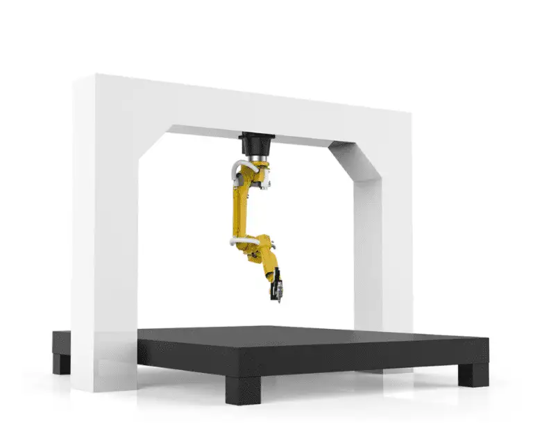
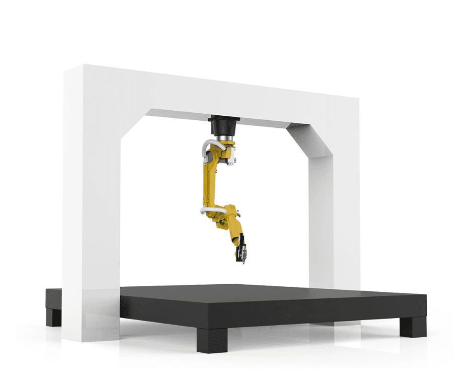
The core of this deployment is the 6-axis collaborative arm integrated with a 3kW fiber laser source. Unlike traditional industrial robots that require massive safety cages and specialized programmers, the Laser Welding Cobot allows our lead welders to “hand-guide” the torch to set waypoints.
The synergy here is critical: Laser Technology provides an incredibly concentrated heat source, but its greatest weakness in manual application is the sensitivity to focal distance and travel speed. By mounting the laser head on a cobot, we achieve the mechanical consistency required to keep the beam at the precise focal point (typically +/- 0.5mm) while maintaining travel speeds that exceed manual MAG welding by a factor of four.
Advancements in Laser Technology for MAG Hybridization
We are utilizing a “Laser-Hybrid” approach. While the fiber laser provides deep penetration through keyhole welding, the MAG component (1.2mm ER70S-6 wire) adds filler metal to manage joint gaps and improve the toe profile of the weld. The Laser Technology used here operates at a 1070nm wavelength, which offers high absorption rates in Carbon Steel welding. This ensures that the energy is not reflected—a common issue with non-ferrous materials—but is instead driven deep into the root of the joint.
Practical Application in Carbon Steel Welding
Material Specifications and Preparation
Our primary focus was on A36 and A516 Grade 70 carbon steel, ranging from 6mm to 12mm in thickness. In traditional MAG welding, these thicknesses require extensive beveling and multiple passes.
With the Laser Welding Cobot, we have shifted to square-butt configurations for thicknesses up to 8mm.
Lesson Learned: Carbon Steel welding with laser assistance requires a higher standard of edge preparation. In the Texas shop, we found that standard plasma-cut edges were occasionally too oxidized. We moved to fiber-laser-cut components or mechanical grinding to ensure the “Laser Technology” could interact with clean base metal, preventing porosity in the root.
Parameter Optimization
During the first two weeks of the Houston field trial, we established the following baseline for an 8mm fillet weld on carbon steel:
- Laser Power: 2.8 kW
- Wire Feed Speed: 450 inches per minute (ipm)
- Travel Speed: 65 inches per minute (ipm)
- Gas Mix: 90% Argon / 10% CO2 (The lower CO2 content helps stabilize the laser plasma cloud).
This setup resulted in a Heat Affected Zone (HAZ) that was 60% narrower than our previous pulse-MAG process. For Carbon Steel welding, a narrower HAZ means significantly less thermal distortion—a massive win for the downstream assembly of long structural beams.
The “Texas Factor”: Environmental and Operational Realities
Managing Thermal Loads in High Ambient Heat
Deploying a Laser Welding Cobot in a non-climate-controlled Texas facility in July requires specific cooling infrastructure. We found that standard chillers were struggling to maintain the laser source temperature. We had to upgrade to a dual-circuit high-capacity chiller and insulate the fiber delivery cable to prevent “thermal lensing” issues. If the Laser Technology overheats, the beam profile shifts, leading to inconsistent penetration in the Carbon Steel welding process.
Safety and Training in a Collaborative Space
The “Cobot” designation suggests safety, but when you introduce Laser Technology, you are dealing with a Class 4 laser hazard. Even though the robot is collaborative, the beam is not. We implemented a “Laser Area” with interlocked curtains.
Field Observation: The veteran welders were initially skeptical. However, once they saw the Laser Welding Cobot handle the repetitive 10-foot longitudinal seams without stopping, the narrative changed from “replacing me” to “doing the grunt work for me.”
Comparative Analysis: Manual MAG vs. Laser Welding Cobot
Throughput and Efficiency
In a standard 10-hour shift, a manual welder on our floor was producing approximately 45 linear feet of high-quality weld. The Laser Welding Cobot, once dialed in, produced 180 linear feet in the same timeframe. The speed of Laser Technology combined with the 95% arc-on time of the cobot creates a throughput curve that traditional methods cannot match.
Consumable Reduction
Because the Laser Welding Cobot utilizes the laser for the bulk of the penetration, we reduced our wire consumption by 35% per foot of weld. In Carbon Steel welding, wire cost adds up quickly. Furthermore, the reduction in post-weld grinding (due to zero spatter) saved us an estimated 15 man-hours per week.
Lessons Learned and Engineering Recommendations
1. Fit-up is Non-Negotiable
The precision of Laser Technology is a double-edged sword. While a manual welder can “wiggle” the torch to bridge a 2mm gap, the Laser Welding Cobot requires tighter tolerances. We had to retrain our tacking crew to ensure gaps did not exceed 0.5mm. We are currently looking into “seam tracking” sensors to allow the cobot to adjust in real-time, which will make the system more robust for field-prepped Carbon Steel welding.
2. Shielding Gas Dynamics
High-speed welding creates a venturi effect that can pull in atmospheric oxygen. We moved to a specialized “trailing shield” nozzle on the cobot head. This ensured that the Carbon Steel welding pool remained protected until it cooled below the oxidation temperature, which is critical when traveling at 60+ ipm.
3. Data Logging for Quality Control
One of the best features of the modern Laser Welding Cobot is the ability to log every weld parameter. For the energy sector, traceability is vital. We now have a digital “birth certificate” for every structural joint, documenting the exact laser wattage and wire speed used. This has simplified our NDT (Non-Destructive Testing) workflow significantly.
Conclusion
The integration of the Laser Welding Cobot at our Texas site has successfully bridged the gap between high-end Laser Technology and practical, heavy-duty Carbon Steel welding. While the initial setup required a strict adherence to joint fit-up and environmental cooling, the ROI is manifest in the 4x increase in linear output and the superior metallurgical properties of the welds.
Moving forward, we recommend the transition of all structural fillet lines to this cobot-assisted laser process. The era of “brute force” MAG welding is ending; the precision of the laser is the new standard for the Texas fabrication industry.
End of Report.
Prepared by: Senior Welding Engineer, Technical Division