Engineering Review: Robotic MIG/MAG Welding Robot – Gurgaon, India
In this article
- Field Commissioning Report: Robotic MIG/MAG Integration for Galvanized Steel (Gurgaon Industrial Area)
- Project Overview and Site Conditions
- The Role of the MIG/MAG Welding Robot in Modern Production
- Integrating Advanced Arc Welding Solutions
- Technical Deep-Dive: Challenges in Galvanized Pipe Welding
- System Synergy and Parameter Optimization
- Lessons Learned from the Field
- Conclusion
Field Commissioning Report: Robotic MIG/MAG Integration for Galvanized Steel (Gurgaon Industrial Area)
Project Overview and Site Conditions
This report summarizes the deployment and optimization of a high-speed production cell at a Tier-1 automotive component manufacturer in Gurgaon, Haryana. The objective was the transition from manual stations to a fully automated **MIG/MAG Welding Robot system to handle structural chassis components, specifically focusing on the challenges inherent in Galvanized Pipe welding**.
Gurgaon’s industrial climate presents unique challenges. During the commissioning phase in the pre-monsoon heat, ambient shop floor temperatures frequently exceeded 42°C with humidity levels spiking above 70%. These environmental factors necessitated a rigorous evaluation of the cooling systems for both the robot controllers and the power sources. Furthermore, the local power grid stability in the Manesar-Gurgaon belt required the integration of heavy-duty industrial voltage stabilizers to prevent logic errors in the robot’s CPU and fluctuations in the arc voltage.
The Role of the MIG/MAG Welding Robot in Modern Production
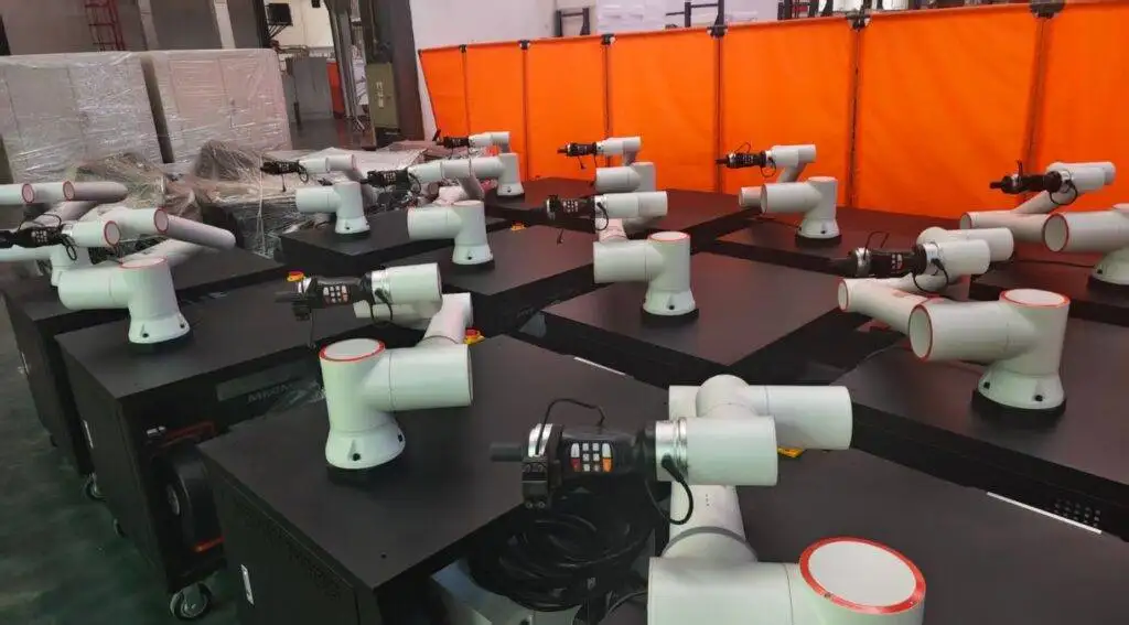
The core of this installation is a 6-axis industrial MIG/MAG Welding Robot with a 1440mm reach and a 6kg payload. In the context of the Gurgaon facility, the robot serves as the primary driver of cycle time consistency. Unlike manual operators, who struggle with the toxic fumes and erratic spatter characteristic of galvanized materials, the robotic arm maintains a constant torch angle and travel speed—variables that are critical when the material chemistry is working against the weld pool.
We utilized a hollow-wrist design to minimize cable wear. This is a crucial “lesson learned” from previous Gurgaon installs: in high-duty cycle environments, external dress packs often snag on custom jigs, leading to downtime. By routing the torch cables through the center of the wrist, we achieved a 360-degree rotation capability without stress on the wire liner, which is vital for the circumferential welds required on round pipe sections.
Integrating Advanced Arc Welding Solutions
A robot is only as capable as the electricity it directs. To achieve high-quality joins on coated steels, we implemented specialized Arc Welding Solutions that go beyond standard CV (Constant Voltage) power. We utilized a digital inverter power source capable of high-speed pulsing and modified short-circuit transfer.
The synergy between the MIG/MAG Welding Robot and these Arc Welding Solutions is managed via a high-speed EtherCAT communication bridge. This allows the robot controller to adjust welding parameters in real-time based on the TCP (Tool Center Point) speed. In Gurgaon’s high-volume environment, the “Solution” aspect refers to the software-driven waveforms specifically tuned for the 20-micron zinc coating on the workpieces. By utilizing a “Pulse-on-Pulse” regime, we were able to oscillate the heat input, allowing the zinc vapor to escape the molten pool before the trailing edge of the weld solidified.
Technical Deep-Dive: Challenges in Galvanized Pipe Welding
Galvanized Pipe welding is notoriously difficult due to the low boiling point of zinc (approximately 906°C) compared to the melting point of steel (approximately 1500°C). When the arc hits the galvanized layer, the zinc turns to gas instantly. If the weld pool solidifies too quickly, this gas is trapped, resulting in “wormhole” porosity and excessive spatter.
1. Porosity Mitigation Strategies
In this field application, we found that traditional CO2 shielding was insufficient. We shifted to an 80% Argon / 20% CO2 mixture. The Argon provides the necessary arc stability for the MIG/MAG Welding Robot, while the CO2 provides the surface tension required to keep the puddle fluid just long enough for the zinc gas to vent.
2. Spatter Management
Zinc-induced spatter is the primary cause of downtime in robotic cells due to nozzle buildup. To counter this, we integrated an automated torch cleaning station (reamer) into the robot’s routine every five cycles. Additionally, we applied a ceramic-based anti-spatter spray through an automated venturi system integrated into the reamer. This ensured that the Arc Welding Solutions remained effective without constant manual intervention to clean the gas shroud.
System Synergy and Parameter Optimization
The real-world success in the Gurgaon plant stemmed from the interplay between the motion control of the MIG/MAG Welding Robot and the feedback loops of the Arc Welding Solutions. We discovered that a “push” angle of 10 to 15 degrees was optimal for Galvanized Pipe welding. This technique allows the arc force to drive the zinc vapors ahead of the weld pool.
Field Parameter Set-up:
* Wire: 1.2mm ER70S-6 (Silicon-Manganese deoxidizers are essential here).
* Wire Feed Speed: 8.5 m/min.
* Travel Speed: 45 cm/min (Slower than black-steel speeds to allow outgassing).
* Voltage Offset: +1.2V above the synergic curve to widen the arc bridge.
By fine-tuning the start-and-stop sequences—specifically the “burn-back” settings and the “crater fill” routine—we eliminated the cracking issues often found at the end of pipe circumference welds. The Arc Welding Solutions provided a “Hot Start” function that momentarily boosted current at the strike point to clear the zinc layer, ensuring immediate fusion with the base steel.
Lessons Learned from the Field
After 400 hours of operation at the Gurgaon site, several technical realities became clear that are often omitted from the manufacturer’s manuals:
Grounding and Interference
In many Indian industrial zones, the factory “earth” can be “noisy” due to neighboring heavy machinery. We experienced intermittent arc-start failures until we installed a dedicated copper earth pit for the MIG/MAG Welding Robot. Proper grounding is non-negotiable for digital Arc Welding Solutions to prevent signal clipping.
Wire Quality Matters
Given the humidity in Gurgaon, wire oxidation is a rapid process. We switched to bulk-pack “marathon” drums with vapor-phase inhibitor (VPI) covers. This kept the wire surface clean, reducing friction in the liners and preventing copper-coating flaking, which can clog the contact tip and cause “bird-nesting” at the feeder.
The Human Element in Automation
Even with the best MIG/MAG Welding Robot, the operators must be trained in “robotic-grade” fit-up. Galvanized Pipe welding is intolerant of gaps exceeding 10% of the wall thickness. We implemented a new jigging standard with pneumatic clamping to ensure zero-gap fit-up, which allowed the Arc Welding Solutions to perform consistently without searching for the root.
Conclusion
The installation in Gurgaon demonstrates that the transition to robotic welding is not merely about replacing a hand with a machine. It is about the technical integration of a high-precision MIG/MAG Welding Robot with specialized Arc Welding Solutions capable of handling the volatile physics of Galvanized Pipe welding.
By addressing the zinc outgassing through waveform manipulation and ensuring the robotic motion was optimized for the local environmental conditions, we achieved a 35% increase in throughput and a 90% reduction in post-weld rework. For senior engineers, the takeaway is clear: focus on the gas-metal interface and never underestimate the impact of local site conditions on high-end electronics.
Report End.
*Author: Senior Welding Engineer (Materials & Automation)*
*Location: Gurgaon, India*