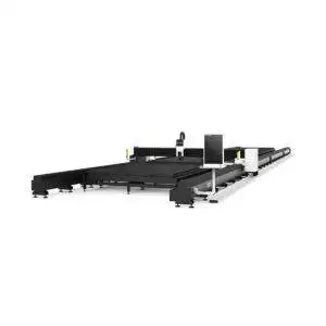
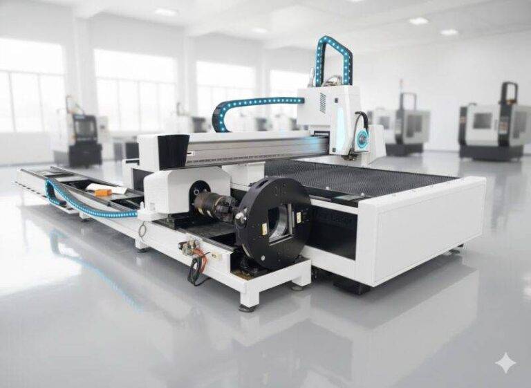
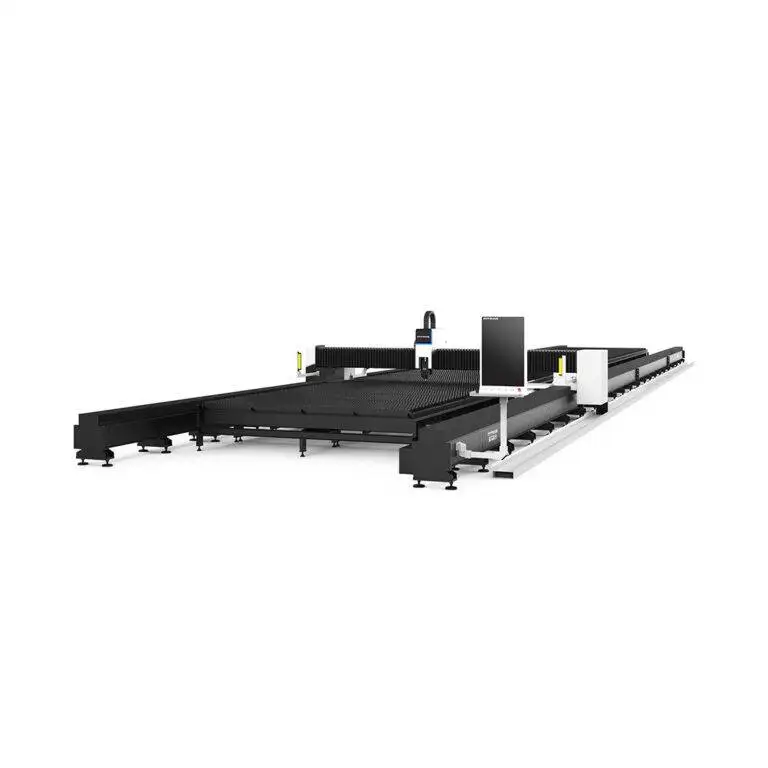
Fiber Laser Cutting Machine with Zero-tailing technology for Bridge Trusses
In this article
- Optimizing Bridge Truss Fabrication via Fiber Laser Technology
- The Mechanics of Zero-Tailing in Large-Scale Profiles
- Precision Beam Delivery and Kerf Management
- Consolidated Workflow: Punching, Marking, and Cutting
- Elimination of Secondary Grinding Processes
- Thermal Control and Structural Integrity
- Data Integration and Industry 4.0 Compatibility
- Economic Impact of Zero-Tailing Implementation
- Conclusion
Optimizing Bridge Truss Fabrication via Fiber Laser Technology
In the realm of structural engineering, the fabrication of Bridge Trusses demands a convergence of extreme precision and material efficiency. Traditional methods often suffer from excessive scrap rates and the requirement for labor-intensive secondary processing. The implementation of high-power Fiber Laser Cutting systems, specifically those engineered with Zero-tailing technology, represents a fundamental shift in production philosophy. This approach prioritizes the reduction of the heat-affected zone (HAZ) and the maximization of Material Utilization through advanced mechanical clamping and beam delivery systems.
The Mechanics of Zero-Tailing in Large-Scale Profiles
Zero-tailing, or zero-scrap technology, is achieved through a multi-chuck synchronized movement system. In standard laser pipe cutting, a significant portion of the trailing end of the tube cannot be processed because the chuck must maintain a grip on the material to ensure rotational stability. This results in a “tail” or “remnant” that is typically discarded. In bridge truss manufacturing, where heavy-duty H-beams, square tubes, and circular hollow sections (CHS) are utilized, these remnants represent a substantial financial loss.
Four-Chuck Synchronized Motion
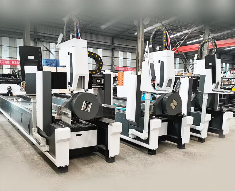
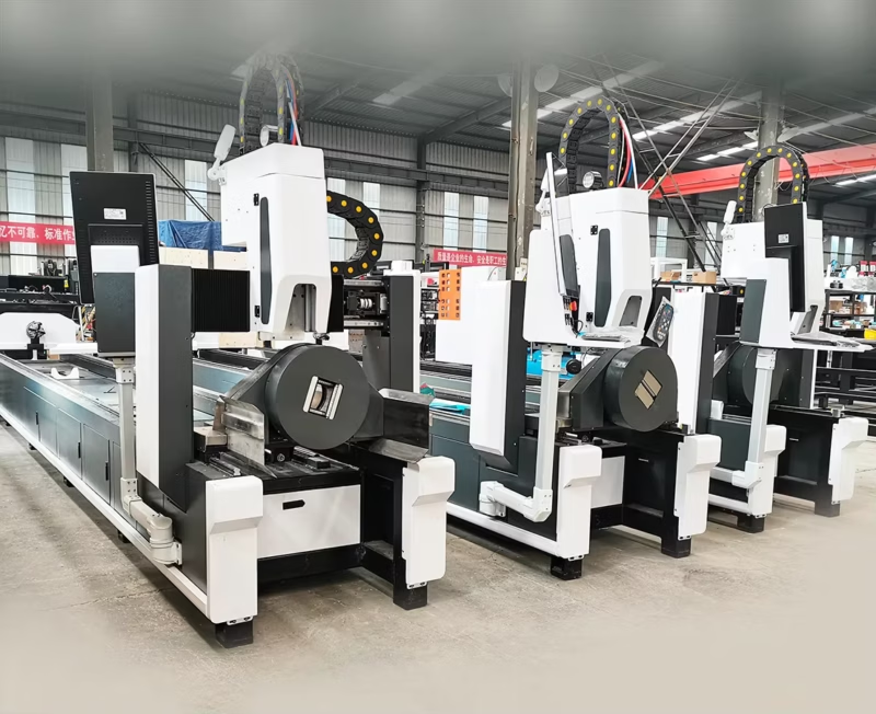
The industrial-grade fiber laser machines utilized for bridge components employ a four-chuck configuration. This setup allows for the real-time handover of the workpiece between chucks. As the laser head approaches the final segment of the profile, the rear chucks advance while the lead chucks maintain tension and positioning. This enables the laser to cut the entire length of the raw material, effectively reducing the scrap end to nearly zero millimeters. From an industrial engineering perspective, this increases the yield per raw material unit by 5% to 15%, depending on the profile length and complexity.
Precision Beam Delivery and Kerf Management
Fiber lasers operate at a wavelength of approximately 1.06 microns, allowing for a much smaller focal spot compared to older CO2 technologies. for Bridge Trusses, this precision is vital. The trusses rely on tight-tolerance joints where the load distribution is calculated based on exact geometry. Fiber Laser Cutting provides a kerf width—the width of the material removed during the cut—that is consistently narrow, usually between 0.1mm and 0.3mm for structural steel thicknesses. This level of accuracy ensures that when truss members are assembled, the gaps are minimal, facilitating superior structural alignment without the need for manual shimming.
Consolidated Workflow: Punching, Marking, and Cutting
One of the primary advantages of fiber laser systems in bridge construction is the ability to consolidate multiple fabrication steps into a single machine cycle. This eliminates the “bottleneck” effect often seen when moving heavy structural members between different workstations.
High-Speed Punching and Hole Geometry
Bridges require thousands of bolt holes for splice plates and gussets. Traditional drilling is slow and generates significant heat and mechanical stress. The fiber laser performs “punching” via high-pressure nitrogen or oxygen-assisted cutting. This process creates holes with perfectly vertical walls and no taper, meeting the stringent requirements for high-strength friction-grip (HSFG) bolts. The speed of laser-drilled holes is exponentially faster than mechanical drilling, reducing the cycle time per truss member by up to 60%.
Automated Marking for Assembly Guidance
Complex bridge trusses involve numerous nodes and interconnecting parts. Modern fiber laser systems utilize low-power etching to “mark” assembly instructions, part numbers, and alignment lines directly onto the steel surface. Because this marking is performed in the same coordinate system as the cutting, the placement is accurate to within microns. This removes the risk of human error in manual layout and ensures that every component is oriented correctly during the final assembly phase.
Elimination of Secondary Grinding Processes
In bridge fabrication, the quality of the cut edge is directly linked to the fatigue life of the structure. Micro-cracks or dross on the underside of a cut can act as stress concentrators. High-power fiber lasers, when tuned correctly with optimal auxiliary gas pressure, produce an “as-cut” surface finish that requires no further grinding. The edge roughness (Rz) is kept within the limits specified by structural codes such as AWS D1.5 or Eurocode 3. By eliminating the grinding stage, manufacturers reduce labor costs and avoid the introduction of mechanical heat that could alter the temper of the steel near the joint area.
Thermal Control and Structural Integrity
Industrial engineers must account for the Heat Affected Zone (HAZ) in bridge design. Excessive heat can lead to local hardening or softening of the steel, potentially compromising the truss’s ability to handle dynamic loads. Fiber Laser Cutting minimizes the HAZ due to its high power density and rapid cutting speeds. The energy is concentrated on such a small area for such a short duration that the surrounding material remains relatively cool. This preserves the metallurgical properties of the high-tensile steel commonly used in bridge construction, such as S355 or S460 grades.
Data Integration and Industry 4.0 Compatibility
The modern fiber laser machine is not a standalone tool but a node in a digital manufacturing ecosystem. CAD/CAM software specifically designed for bridge trusses can export complex nesting patterns directly to the laser’s CNC controller. Zero-tailing technology is integrated into the nesting logic, calculating the exact chuck positions required to maximize the use of every millimeter of the raw beam. Industrial engineers can track real-time metrics, including gas consumption, cutting time, and material yield, allowing for precise cost estimation and production scheduling.
Economic Impact of Zero-Tailing Implementation
The Return on Investment (ROI) for a zero-tailing fiber laser system is driven by three primary factors: material savings, labor reduction, and throughput increases. In a large bridge project involving 10,000 tons of steel, a 3% increase in Material Utilization through zero-tailing can save hundreds of tons of high-grade structural steel. When combined with the elimination of separate marking and drilling stations, the total cost per ton of fabricated truss is significantly lower than that of traditional methods. Furthermore, the high precision of the laser ensures that the final structure is built to the exact design intent, reducing the likelihood of expensive field corrections or structural failures.
Conclusion
For the modern industrial engineer, the adoption of Fiber Laser Cutting with Zero-tailing technology is an essential evolution in bridge truss production. By integrating cutting, punching, and marking into a high-precision, zero-waste process, manufacturers can achieve unprecedented levels of efficiency and structural reliability. The focus on tight tolerances, minimal thermal impact, and maximum material yield ensures that the resulting infrastructure is not only cost-effective but also engineered to withstand the rigorous demands of long-term service life.