Automatic Girth Seam Welder with Narrow Gap welding for Pressure Vessels
In this article
- Technical Fundamentals of Narrow Gap Girth Seam Welding
- Robotic Integration and Kinematics
- Maintenance Protocols for High-Availability Robotic Systems
- Consumable Life Cycle Management
- Torch Alignment and Calibration
- Labor ROI and Economic Feasibility
- Deposition Rates and Arc-On Time
- Long-Term Human Capital Investment
- Strategic Implementation in the Pressure Vessel Sector
Technical Fundamentals of Narrow Gap Girth Seam Welding
In pressure vessel manufacturing, the girth seam represents a critical structural juncture that must withstand high internal pressures and thermal cycling. Conventional welding techniques often utilize wide-angle V-grooves, requiring massive amounts of filler metal and multiple passes. An Automatic Girth Seam Welder utilizing narrow gap technology changes this paradigm by employing a joint preparation with an opening typically between 5 to 9 degrees. This reduces the total weld metal volume significantly, which directly translates to lower heat input and reduced distortion.
The application of the MAG welding process (Metal Active Gas) within this narrow geometry requires precise control over arc oscillation and wire positioning. Because the side-wall fusion is paramount in narrow gap configurations, the robotic system must execute a specific weave pattern or use a “bead-on-bead” strategy to ensure zero defects at the fusion line. This engineering approach prioritizes metallurgical integrity while optimizing the duty cycle of the welding power source.
Robotic Integration and Kinematics
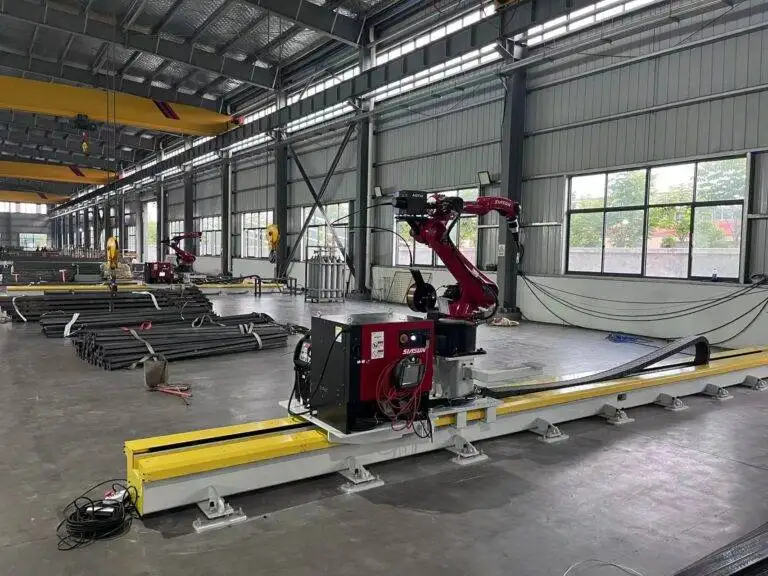
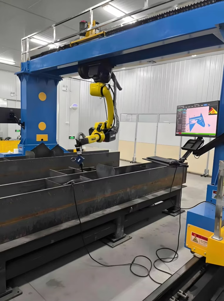
The robotic arm in a girth seam setup is usually mounted on a linear track or a column-and-boom manipulator. The primary advantage of robotics in this sector is the ability to maintain a constant torch angle and standoff distance throughout the entire circumference of the vessel. Unlike manual welding, where operator fatigue leads to fluctuations in travel speed and arc length, the robot provides a steady-state deposition rate. The integration of narrow gap welding sensors, such as through-arc sensing or laser-based seam tracking (used purely for navigation), ensures that the robot compensates for any eccentricities in the vessel rotation or minor deviations in the bevel preparation.

MAG Process Optimization for Heavy Wall Vessels
MAG welding in a narrow gap requires a specialized torch design. To reach the bottom of a deep groove (which can exceed 100mm in some pressure vessels), the gas nozzle must be slimmed down without compromising shielding gas coverage. Laminar flow is essential here; any turbulence within the narrow gap can pull in atmospheric nitrogen or oxygen, leading to porosity. Engineers must calibrate the gas flow rates specifically for the groove depth, often utilizing argon-CO2 mixes to achieve the necessary penetration profiles while maintaining a stable spray transfer mode.
Maintenance Protocols for High-Availability Robotic Systems
From an industrial engineering perspective, the uptime of an automatic girth seam welder is the most critical metric for calculating facility throughput. Because narrow gap MAG welding involves high current densities and long “arc-on” times, the wear and tear on consumables is accelerated. A structured maintenance schedule is non-negotiable for preventing unplanned downtime.
Consumable Life Cycle Management
The contact tip is the most frequent point of failure. In a robotic MAG setup, the “keyholing” of the contact tip occurs due to the constant friction of the wire electrode. If the orifice becomes elongated, the arc center shifts, which in a narrow gap of only 8mm can result in a lack of side-wall fusion. Systems should be equipped with automatic tip cleaners and scheduled replacements based on the number of meters of wire fed. Similarly, the wire feed liners must be blown out or replaced every 500kg of wire to prevent friction-induced feed motor strain, which causes arc instability.
Torch Alignment and Calibration
Robotic precision is only as good as its TCP (Tool Center Point) calibration. In girth seam welding, the torch is subjected to significant radiant heat. Thermal expansion of the torch neck can shift the TCP by 1-2mm, which is catastrophic in a narrow gap. Industrial engineers should implement a daily automated TCP check station where the robot touches a reference pointer to verify its coordinates. If a deviation is detected, the system should automatically recalibrate before commencing the next weld pass.
Cooling System Integrity
High-amperage MAG welding generates heat levels that can degrade the internal insulation of the robotic torch. Water-cooling units must be monitored for flow rate and conductivity. High conductivity in the coolant can lead to electrolysis within the torch body, causing internal leaks. Using deionized water and specialized coolants is mandatory for systems running at 400A or higher on a 100% duty cycle.
Labor ROI and Economic Feasibility
The shift from manual to robotic girth seam welding is often driven by the labor ROI analysis. In the current industrial landscape, the scarcity of coded welders capable of performing multi-pass MAG welding on thick-walled pressure vessels has driven labor costs to peak levels. A robotic system does not replace the welder but shifts their role from a manual laborer to a system technician.
Deposition Rates and Arc-On Time
A manual welder typically achieves an arc-on time of 20% to 30% due to the need for breaks, repositioning, and cleaning. An automated robotic system can maintain an arc-on time of 75% to 85%. When combined with narrow gap geometry, which requires 40-60% less filler metal, the time-to-completion for a single girth seam can be reduced by as much as 70%. This allows a facility to increase its annual vessel output without expanding the physical footprint of the shop floor.
Comparative Cost Analysis
Consider a vessel with a 50mm wall thickness. A standard V-groove might require 25 passes. A narrow gap robotic system might complete the same joint in 12 passes with higher travel speeds. The reduction in wire consumption, shielding gas, and electrical power per joint directly impacts the bottom line. Furthermore, the reduction in post-weld rework—since robots do not suffer from the “Friday afternoon” fatigue that causes human error—virtually eliminates the costs associated with gouging out and repairing defective weld sections.
Long-Term Human Capital Investment
While the initial capital expenditure (CAPEX) for a robotic girth seam welder is high, the payback period is typically between 18 and 24 months in high-volume environments. The transition also improves workplace safety. By removing the operator from the immediate vicinity of the arc and the associated fumes and heat, the company reduces long-term liability and improves employee retention. The technician oversees the process from a control console, focusing on parameter optimization rather than the physical strain of manual welding.
Strategic Implementation in the Pressure Vessel Sector
To successfully integrate an automatic girth seam welder, the engineering department must standardize the upstream processes. Narrow gap welding is less tolerant of poor fit-up than traditional V-grooves. The vessel shells must be rolled to tighter tolerances, and the edge preparation must be machined rather than hand-ground. This requirement for precision forces a higher level of discipline throughout the entire manufacturing chain, leading to a general improvement in product quality.
In conclusion, the synergy between narrow gap geometry and robotic MAG welding offers a sophisticated solution for modern pressure vessel fabrication. By focusing on high-precision motion control, rigorous maintenance of the welding head, and a clear understanding of the labor-to-output ratio, manufacturers can achieve significant competitive advantages. The transition to automation is not merely a technological upgrade but a strategic shift toward data-driven, repeatable, and highly efficient industrial production.