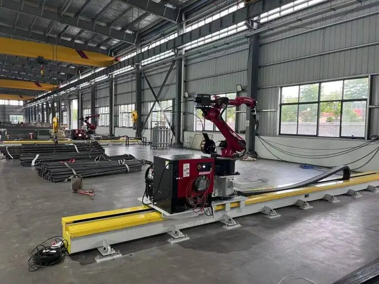
Automatic Girth Seam Welder with Offline Programming for Bridge Trusses

In this article
- Optimizing Bridge Truss Fabrication through Automated Girth Seams
- Offline Programming (OLP) and Digital Workflow Integration
- Eliminating Non-Productive Robot Time
- Sensor Integration and Path Correction
- Technical Specifications of the MAG Process in Heavy Trusses
- Maintenance Protocols for Robotic Welding Cells
- Labor ROI and Economic Impact Analysis
- Cost Benefit Breakdown
- Conclusion
Optimizing Bridge Truss Fabrication through Automated Girth Seams
In the sector of structural steel fabrication, the girth seam weld represents a critical junction in bridge truss assemblies. These joints, often found at the intersection of hollow structural sections (HSS) or cylindrical chords and web members, demand absolute penetration and geometric precision to withstand dynamic loading. Traditionally, these welds were executed manually, a process fraught with ergonomic challenges and variable weld quality. The introduction of the automatic Girth Seam Welding system, paired with a multi-axis robotic arm, shifts the manufacturing paradigm from manual craftsmanship to precision engineering.
Industrial efficiency in bridge work is measured by the arc-on time and the minimization of rework. By utilizing a robotic system, the fabrication shop can maintain a consistent duty cycle that manual operators cannot replicate over an eight-hour shift. The system typically employs a rotary positioner synchronized with a 6-axis robot, allowing for a continuous weld bead around the circumference of the truss member. This synchronization ensures that the weld pool remains in the optimal flat or horizontal-fillet position, significantly reducing the risk of slag inclusions or porosity.
Offline Programming (OLP) and Digital Workflow Integration
The primary bottleneck in robotic adoption has historically been the downtime associated with “teach-pendant” programming. for Bridge Trusses, which may vary in length, diameter, and joint configuration, manual programming on the shop floor is economically unfeasible. Offline Programming (OLP) solves this by allowing engineers to create, simulate, and debug welding paths in a virtual 3D environment using CAD metadata.
Eliminating Non-Productive Robot Time
With OLP, the robot remains in production on one task while the welding engineer prepares the parameters for the next truss assembly. The software calculates the complex kinematics required for the robot to navigate the intersection of diagonal members without collisions. This “digital twin” approach allows for the verification of torch angles and reach limitations before a single spark is struck. By the time the physical workpiece is loaded onto the rotary positioner, the program is ready for execution, reducing setup times by up to 85 percent.
Sensor Integration and Path Correction
Despite the precision of OLP, real-world material tolerances and fit-up variations in heavy steel can occur. Advanced Automatic Girth Seam Welders utilize “Touch Sensing” and “Through-Arc Seam Tracking” (TAST). The robot uses the welding wire or a dedicated probe to locate the exact start point of the girth seam. During the MAG process, the system monitors electrical arc characteristics to make real-time micro-adjustments to the torch path, ensuring the bead stays centered in the joint despite any thermal distortion.
Technical Specifications of the MAG Process in Heavy Trusses
The Metal Active Gas (MAG) welding process is the preferred method for bridge truss fabrication due to its high deposition rates and deep penetration capabilities. When automated, the MAG process utilizes specialized power sources capable of pulsed-spray transfer, which minimizes spatter and controls heat input into the high-strength low-alloy (HSLA) steels common in bridge construction.
Gas Shielding and Wire Feed Dynamics
For girth seams on thick-walled pipe or box sections, a mix of Argon and CO2 is standard. The robotic interface allows for precise control over the gas flow rate, ensuring the weld pool is protected even at high travel speeds. The wire drive system must be a heavy-duty, four-roll unit to prevent slipping, especially when feeding large-diameter flux-cored or solid wires over the extended reaches required for large truss segments.
Thermal Management
Bridge components are sensitive to the Heat Affected Zone (HAZ). Automated systems allow for the exact calculation of heat input (kJ/mm), which is vital for maintaining the mechanical properties of the base metal. By maintaining a constant travel speed and optimized voltage, the robotic girth seam welder ensures that the cooling rate is controlled, preventing the formation of brittle martensitic structures in the weld metal.
Maintenance Protocols for Robotic Welding Cells
System reliability is contingent upon a rigorous preventive maintenance schedule. Unlike manual equipment, a robotic cell has high-precision mechanical components that require specific calibration.
Torch and Consumable Management
The most frequent maintenance point is the welding torch. Automatic reaming stations should be integrated into the cell to clean the nozzle of spatter at set intervals. Contact tips must be replaced based on wire throughput metrics rather than failure, as wear on the tip can cause “keyholing,” which destabilizes the arc and shifts the tool center point (TCP).
Calibration of Rotary Axis
The girth seam welder relies on the perfect alignment of the rotary positioner (external axis) and the robot’s base. Quarterly calibration checks using laser alignment tools ensure that the synchronization remains within the required 0.1mm tolerance. Lubrication of the robot’s reduction gears and the positioner’s slewing ring is essential to prevent backlash, which would manifest as irregularities in the girth seam bead profile.
Labor ROI and Economic Impact Analysis
The Return on Investment (ROI) for an automatic girth seam welder is realized through three primary channels: labor productivity, consumable savings, and quality assurance.
From a labor perspective, the goal is not merely the replacement of staff but the elevation of the workforce. One skilled operator can manage two or three robotic cells, overseeing the loading, OLP execution, and visual inspection. In manual environments, a girth seam on a large diameter truss might take four hours of highly fatiguing work; a robotic cell can often complete the same task in less than 90 minutes with 100 percent repeatability.
Cost Benefit Breakdown
1. Deposition Efficiency: Manual MAG welding typically operates at a 30-40% duty cycle. Robotic systems regularly achieve 75-85% duty cycles. This doubling of “arc-on” time directly halves the labor cost per foot of weld.
2. Consumable Reduction: Because the robot follows an optimized path defined by OLP, over-welding (applying more metal than specified) is eliminated. In bridge trusses, reducing a 12mm fillet weld to the specified 10mm can save thousands of dollars in wire and gas over a single project.
3. Inspection and Rework: The consistency of robotic MAG welding significantly reduces the failure rate during Non-Destructive Testing (NDT), such as ultrasonic or radiographic inspection. Removing the need for carbon arc gouging and re-welding defective manual seams provides an immediate boost to the project’s bottom line.
Conclusion
Implementing an automatic girth seam welder with Offline Programming is a strategic necessity for modern structural steel firms specializing in bridge trusses. By leveraging OLP to maximize machine uptime and focusing on the technical strengths of the MAG process, manufacturers can secure a significant competitive advantage. The transition yields a quantifiable ROI through increased throughput and the mitigation of human error, ensuring that the critical infrastructure of tomorrow is built with verifiable precision and optimal resource efficiency.