Automate complex 3D paths with 6-axis robotic precision. Perfect for curved surfaces and irregular components—no custom dies required.
3D Precision: Clean, burr-free fiber laser cutting on non-planar surfaces.
Auto-Tracking: Non-contact sensor maintains perfect focus on uneven plates.
Flexibility: Replaces manual grinding and expensive trimming tools.
Ready for 3D: Direct CAD/CAM & Offline Programming support.
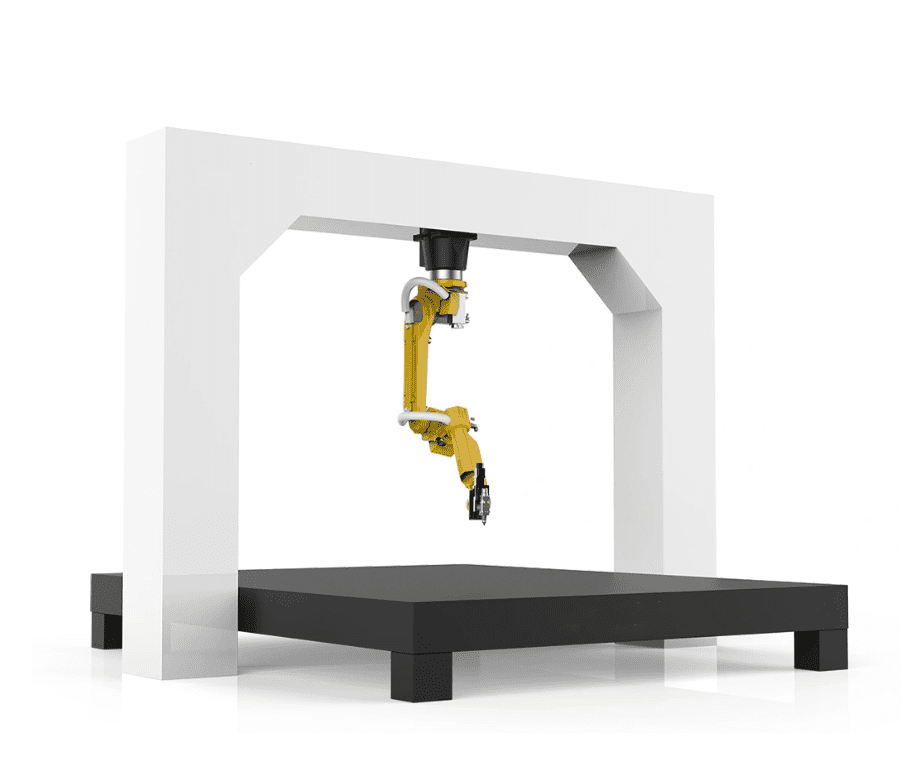
6-Axis 3D Robotic Fiber Laser System
Precision Automation for Complex Irregular Plates
3D Path Intelligence
Beyond 2D limitations. Our system navigates complex spatial paths to process spherical, corrugated, and multi-angled plates.
Material Versatility
Optimized for Carbon Steel, Stainless, and Aluminum. The Fiber Laser source ensures rapid, high-quality dross-free edges.
The Solution for Complex Plate Fabrication
The PCL 3D Robotic Fiber Laser System is specifically engineered to bridge the gap between traditional flatbed laser cutting and manual secondary processing. In modern manufacturing, many workpieces—such as automotive chassis components and custom panels—feature irregular shapes and non-planar surfaces.
Our system utilizes a 6-axis industrial robotic arm integrated with a high-performance Fiber Laser cutting head. By employing a high-response capacitive height-following sensor, the machine maintains a perfectly consistent focal length across uneven surfaces, ensuring a uniform, clean cut across the entire geometry.
Key Capabilities:
- Precision Trimming: Ideal for cleaning up over-sized stamped parts.
- 3D Feature Cutting: Effortlessly cut bolt holes into curved sections.
- Miter & Beveling: Supports complex weld preparations (V/Y bevels).
- Flexible Workflow: Reduces need for expensive custom trimming dies.
Intelligent Offline Programming
PCL provides advanced Offline Programming (OLP) software. Directly import 3D CAD models (STEP, IGES) to automatically generate cutting trajectories and detect collisions before production begins.
Detailed System Specifications
| Cutting Object | Irregular Plates, Stamped Parts, Curved Surfaces |
| Laser Technology | Fiber Laser (1000W – 4000W High-Stability Source) |
| Robotic System | Heavy-Duty 6-Axis (Standard Reach 2010mm to 3100mm) |
| Motion Accuracy | ±0.03mm Repeatability | ±0.05mm Positioning |
| Tracking Technology | Non-Contact Capacitive Auto-Height Sensing |
| Max Cutting Speed | Up to 30m/min (Depends on Thickness & Power) |
| Software Interface | 3D OLP (Offline Programming) / CAD-CAM Integration |

Advanced Programming: OLP vs. Teaching-Free System
For large-scale gantry welding, manual "point-to-point" teaching is inefficient. PCL offers two cutting-edge solutions to minimize downtime and maximize precision. Understanding the difference is key to choosing the right automation level for your factory.
Off-line Programming (OLP)
OLP allows engineers to create welding paths in a 3D virtual environment using CAD data (STEP/IGES).
- Zero Downtime: Program the next job on a PC while the robot is still welding.
- Collision Detection: Simulates the gantry movement to prevent accidents in a virtual space.
- Best For: Complex workpieces with high repeat rates and detailed weld joints.
Teaching-Free Welding System
Uses 3D laser scanning or vision sensors to "see" the workpiece and generate paths automatically without any CAD data.
- Instant Setup: No manual coding or 3D modeling required; just scan and weld.
- High Flexibility: Ideal for "One-off" parts where every workpiece is slightly different.
- Real-time Adaptation: Automatically compensates for thermal distortion and fit-up gaps.
- Best For: Custom fabrication, repairs, and low-volume/high-mix production.
| Feature | Off-line Programming (OLP) | Teaching-Free System |
|---|---|---|
| Input Required | CAD 3D Models | 3D Laser Scanning |
| Programming Time | Minutes to Hours (Off-site) | Seconds (On-site) |
| Ideal Production | Mass Production / Batch Work | Custom / Single Unit Work |
Related products
-


2in1 fiber laser cutting machine
-


Cobotic Welding Station
-

Gantry welding robot solution
-

Tracked Wheeled AGV Welding robot
-

LFH6020 Fiber laser cutting machine
-
LFP6020
-

robotic welidng machine
-

GF laser cutting machine
-
LFP3015 Fiber Laser Cutter
-


Cantilever Welding Robot solution
-
LFH 4020 Fiber Laser Cutting Machine
-
LFP4020
-

SF6060 fiber laser cutting machine
Watch Related Videos
Frequently Asked Questions
Q1: What is the maximum workpiece size a gantry robot can handle?
The primary advantage of a gantry system is its scalability. Unlike fixed-base robots, the gantry rail length can be extended from 6 meters to over 30 meters. We customize the X, Y, and Z travel strokes based on your specific components, such as trailer chassis or large pressure vessels.
Q2: How does the robot handle material deviations or heat deformation?
For large workpieces, we recommend integrating Laser Seam Tracking or Arc Sensors. These technologies allow the robot to detect the actual weld joint position in real-time and adjust the torch path automatically, compensating for thermal distortion or fit-up tolerances.
Q3: Which robot brands are compatible with the PCL Gantry System?
Our gantry structures are highly flexible and can be integrated with leading international brands including Fanuc, ABB, Yaskawa, and KUKA, as well as our proprietary PCL robotic arms. We provide the full integration including the synchronized 7th or 8th external axes.
Q4: Is it difficult to program a gantry robot for complex large structures?
Not at all. We offer Off-line Programming (OLP) software. This allows your engineers to simulate the welding process and generate code on a PC using CAD data, significantly reducing machine downtime and preventing potential collisions before the physical welding starts.
Q5: Can one gantry system manage multiple welding stations?
Yes. A common configuration is a dual-station setup. While the robot is welding at Station A, operators can safely load or unload workpieces at Station B. This maximizes the robot's "Arc-on Time" and ensures continuous production flow.
