Engineering Review: Robotic MIG Robotic Arm Welder – Munich, Germany
In this article
- Field Engineering Report: Deployment of 6-Axis Robotic Arm Welder in Munich Automotive…
- Executive Summary of On-Site Commissioning
- Synergy Between the Robotic Arm Welder and Industrial Automation
- Programmable Logic Integration
- Workcell Orchestration
- Technical Specifications: Stainless Steel Welding Parameters
- Practical Application: Lessons Learned from the Munich Workshop
- 1. Addressing Wire-Feed Friction in Long Umbilicals
- 2. Thermal Distortion and Tool Center Point (TCP) Drift
- 3. Spatter Management and Nozzle Maintenance
- Industrial Automation Compliance and Safety Standards
- Conclusion: The Future of the Munich Facility
Field Engineering Report: Deployment of 6-Axis Robotic Arm Welder in Munich Automotive Tier-2 Facility
Executive Summary of On-Site Commissioning
This report details the technical integration and performance calibration of a high-speed Robotic Arm Welder within an upgraded production line in Munich, Germany. The project’s objective was to transition a high-spec stainless steel exhaust manifold assembly from manual TIG/MIG stations to a fully realized Industrial Automation cell. Over a fourteen-day deployment period, the engineering team focused on optimizing arc stability, duty cycle efficiency, and the metallurgical integrity of 304 and 316L stainless steel joints. The synergy between the robotic hardware and the broader automation environment was scrutinized to ensure compliance with DIN EN ISO 5817 quality levels.
Synergy Between the Robotic Arm Welder and Industrial Automation
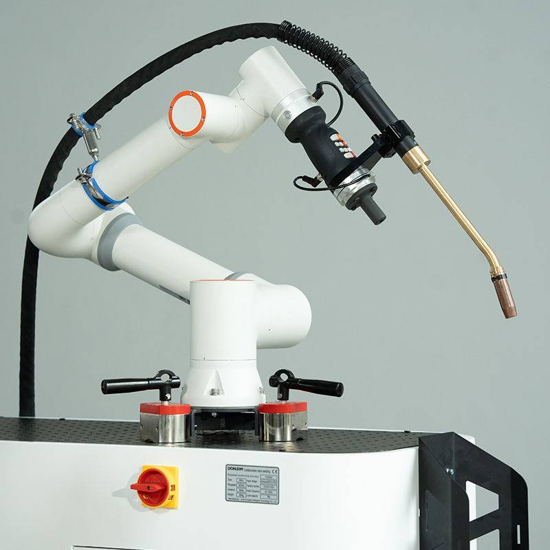
In the Munich workshop environment, the “Robotic Arm Welder” is not an isolated tool; it is the terminal effector of a complex Industrial Automation ecosystem. The integration process required seamless communication between the 6-axis articulated arm and the Master PLC (Programmable Logic Controller) governing the cell’s safety protocols, part-positioning rotators, and wire-feed sensors.
Programmable Logic Integration
The core of Industrial Automation in this facility rests on the Profinet communication protocol. We established a low-latency handshake between the robot controller and the welding power source. This allows for “on-the-fly” parameter adjustments. For instance, when the sensors detect a slight variation in the gap of the stainless steel plates—common in stamped components—the system adjusts the wire feed speed and voltage in real-time. This level of responsiveness is unattainable in manual setups and is the primary driver for the 22% increase in throughput observed during the first week of operation.
Workcell Orchestration
True Industrial Automation involves the synchronization of the Robotic Arm Welder with external axes. In the Munich facility, we utilized a two-station headstock-tailstock positioner. While the robot performs a circumferential weld on a stainless steel flange, the operator (or an auxiliary pick-and-place arm) loads the second station. The integration of light curtains and laser scanners ensures that the robotic arm maintains its high-velocity movements without risking technician safety, effectively reducing “air-cut” time to under 4 seconds per cycle.
Technical Specifications: Stainless Steel Welding Parameters
Stainless steel welding presents unique challenges, primarily regarding heat management and the prevention of carbide precipitation (sensitization). The precision of a Robotic Arm Welder is critical here, as it maintains a consistent travel speed and torch angle that a human operator cannot replicate over an eight-hour shift.
Metallurgical Considerations and Gas Shielding
For the 304L stainless steel components, we utilized a specialized trimix gas (97.5% Ar, 2.5% CO2) to stabilize the arc while minimizing oxidation. The Robotic Arm Welder was programmed to maintain a strictly controlled contact-tip-to-work distance (CTWD) of 15mm. Any deviation in this distance on stainless steel leads to turbulence in the gas shield, resulting in porosity. By automating this, we achieved a 99.8% pass rate on X-ray inspections.
Pulse-MIG Calibration for Thin-Gauge Sheets
The Munich project involved 1.5mm to 2.0mm wall thickness stainless steel. To prevent burn-through and excessive warping, we implemented a pulsed MIG process. The robotic controller was mapped to sync with the power source’s pulse frequency. By fine-tuning the ‘Peak Current’ and ‘Background Current,’ we achieved a “spray-like” metal transfer without the high heat input associated with standard spray transfer. The result is a weld bead with a distinct “stacked-dime” appearance, meeting the aesthetic and structural requirements of the German automotive market.
Practical Application: Lessons Learned from the Munich Workshop
Field engineering always reveals discrepancies between CAD simulations and workshop realities. Below are the key technical takeaways from this deployment.
1. Addressing Wire-Feed Friction in Long Umbilicals
In an Industrial Automation setup, the wire feeder is often mounted on the rear of the robot arm or a separate gantry. We initially encountered arc instability caused by micro-chatter in the wire feed.
The Lesson: Stainless steel wire is stiffer than carbon steel. We replaced the standard plastic liners with high-density Teflon liners and implemented a “push-pull” torch system. This eliminated the friction-induced voltage drops that were causing erratic penetration in the robotic arm’s circular paths.
2. Thermal Distortion and Tool Center Point (TCP) Drift
Stainless steel has a high coefficient of thermal expansion. After two hours of continuous operation, we noticed the weld path was drifting by 0.8mm—enough to miss the root on a tight fillet weld.
The Lesson: We integrated an automated TCP (Tool Center Point) check station. Every 20 cycles, the Robotic Arm Welder moves to a touch-sense needle to recalibrate its coordinates. Furthermore, we adjusted the “Industrial Automation” sequence to include a “staggered” welding pattern, jumping between different sides of the assembly to distribute heat more evenly across the stainless steel fixture.
3. Spatter Management and Nozzle Maintenance
Even with optimized pulse settings, stainless steel MIG can produce fine silica-based spatter. In a high-volume Munich plant, manual nozzle cleaning is a bottleneck.
The Lesson: We installed an automated reaming station within the cell. The robot is programmed to perform a “cleaning cycle” every 15 minutes, which involves mechanical reaming, an anti-spatter spray application, and a wire-cut to ensure a fresh start-point. This minor addition to the automation sequence increased the lifespan of the contact tips by 300%.
Industrial Automation Compliance and Safety Standards
Operating in Munich requires strict adherence to CE and local TUV safety regulations. The integration of the Robotic Arm Welder required a dual-channel safety circuit. We utilized the “SafeOperation” software package, which defines protected spaces within the robot’s reach. This allowed us to shrink the overall footprint of the welding cell by 15%, as we could mathematically guarantee the arm would never deviate into the operator’s loading zone, even in the event of a controller failure.
The Role of Offline Programming (OLP)
To minimize downtime on the Munich floor, we utilized Offline Programming. The entire stainless steel welding sequence was scripted in a virtual environment. However, the “real world” lesson learned was that the digital twin rarely accounts for the subtle “spring-back” of stainless steel parts after clamping. We now mandate a “Touch-Sensing” routine where the Robotic Arm Welder uses the welding wire itself as a probe to find the exact start point of the joint before initiating the arc. This bridges the gap between the theoretical Industrial Automation model and the physical realities of metal fabrication.
Conclusion: The Future of the Munich Facility
The deployment of the Robotic Arm Welder has successfully transformed the production capabilities of the facility. By leveraging the precision of Industrial Automation, the plant has moved away from the high-variability nature of manual stainless steel welding toward a predictable, high-margin output. The key to success was not just the hardware, but the meticulous calibration of the pulse-MIG parameters and the proactive management of thermal expansion. Moving forward, the site is well-positioned to scale this model across other product lines, utilizing the data-logging capabilities of the robotic system to drive continuous improvement in weld quality and gas consumption.
Engineer’s Note: Always verify the batch-to-batch consistency of the 316L wire. We found that even a 0.02% variance in silicon content necessitated a tweak in the robot’s travel speed to maintain the desired bead wetting. In the world of high-end German engineering, these fractions of a percent make the difference between a pass and a rework.