Engineering Review: High-speed MAG MIG/MAG Welding Robot – Gothenburg, Sweden
In this article
- Field Report: Robotic Integration for High-Speed Sheet Metal Fabrication – Gothenburg Industrial…
- 1.0 Introduction and Site Overview
- 2.0 Technical Specifications: The MIG/MAG Welding Robot Implementation
- 3.0 Engineering Arc Welding Solutions for Thin-Gauge Steel
- 4.0 Challenges in Sheet Metal Fabrication Welding
- 5.0 The Gothenburg Synergy: Local Integration and Standards
- 6.0 Lessons Learned and Senior Engineer’s Recommendations
- 7.0 Conclusion
Field Report: Robotic Integration for High-Speed Sheet Metal Fabrication – Gothenburg Industrial Hub
1.0 Introduction and Site Overview
This report summarizes the commissioning and optimization of the MIG/MAG Welding Robot systems at a Tier-1 automotive and marine structural supplier located in Gothenburg, Sweden. The facility specializes in high-volume sheet metal fabrication welding, specifically focusing on 1.5mm to 4.0mm cold-rolled steel and aluminum alloy 5xxx series.
The primary objective was to replace legacy manual stations with automated Arc Welding Solutions to address throughput bottlenecks and inconsistent penetration profiles. In the Gothenburg industrial ecosystem, where Volvo and Polestar standards dictate the quality metrics, the margin for error in weld bead aesthetics and structural integrity is non-existent. Our focus remained on the synergy between high-speed robotic kinematics and advanced power source waveforms.
2.0 Technical Specifications: The MIG/MAG Welding Robot Implementation
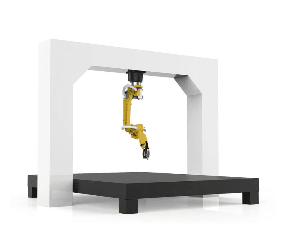
The heart of the cell is a 6-axis high-speed MIG/MAG Welding Robot with a payload capacity of 10kg and a reach of 1440mm. In the context of sheet metal fabrication welding, speed is the primary driver of ROI, but it often conflicts with arc stability.
2.1 Kinematic Calibration and TCP Accuracy
During the first week in Gothenburg, we identified a recurring deviation in the Tool Center Point (TCP) during high-speed air-cut movements. For a MIG/MAG Welding Robot to perform at 120 cm/min travel speeds, the TCP must be maintained within ±0.08mm. We implemented an automatic torch cleaning station with an integrated wire cutter and TCP check sensor.
Lesson Learned: Never rely on the factory calibration for high-speed paths. The centrifugal forces at 100% rapid movement can induce micro-vibrations in the torch neck. We reinforced the bracketry to ensure the arc remained dead-center in the V-groove joints.
2.2 Wire Feed Dynamics
The Swedish winter environment, even in a temperature-controlled workshop, affects wire feed consistency due to humidity fluctuations impacting the lubricant on the wire surface. We transitioned from standard plastic liners to ceramic-coated liners to reduce friction coefficients. This ensured that the MIG/MAG Welding Robot received a constant wire feed speed (WFS) without the “slip-stick” phenomenon that leads to micro-porosity in thin-gauge sheet metal.
3.0 Engineering Arc Welding Solutions for Thin-Gauge Steel
Implementing “off-the-shelf” equipment is rarely enough for specialized Gothenburg contracts. We had to develop bespoke Arc Welding Solutions that integrated the power source’s digital communication protocol directly with the robot controller’s motion engine.
3.1 Pulsed-Arc Waveform Optimization
To prevent burn-through in 1.2mm sheet metal fabrication welding, we utilized a “Modified Short Circuit” (MSC) process. Standard spray transfer generates too much heat, leading to significant workpiece distortion. Our Arc Welding Solutions involved a rapid-pulse frequency (up to 200Hz) which allows for a cooler weld pool while maintaining deep penetration.
Parameters for 2.0mm DC01 Steel:
- Wire: 1.0mm G3Si1
- Gas: 82% Ar / 18% CO2 (M21)
- Peak Current: 240A
- Background Current: 45A
- Travel Speed: 95 cm/min
3.2 Seam Tracking and Adaptive Control
In Gothenburg’s high-precision environments, material batch variations are common. Even a 0.5mm gap in sheet metal can ruin a robotic weld. We integrated a laser-based seam tracker. This is where the synergy between the MIG/MAG Welding Robot and the Arc Welding Solutions becomes critical. The laser sensor scans the joint 20mm ahead of the arc, and the robot’s “Adaptive Fill” software adjusts the WFS and travel speed in real-time to compensate for fit-up gaps.
4.0 Challenges in Sheet Metal Fabrication Welding
Sheet metal fabrication welding is a battle against thermal expansion. During the Gothenburg site visit, we observed that the existing jigs were over-restraining the parts, leading to stress cracking post-weld.
4.1 Heat Input Management
The MIG/MAG Welding Robot allows for “stitch welding” patterns that are impossible to replicate manually with the same consistency. By programming the robot to jump between non-adjacent segments, we redistributed the thermal load. This reduced the global distortion of the 1500mm floor pan assemblies by 60%.
4.2 Spatter Mitigation
Spatter is the enemy of high-speed Arc Welding Solutions. It clogs gas nozzles and ruins the surface finish of the sheet metal. By fine-tuning the “Electronic Inductance” in the power source settings, we achieved a nearly spatter-free transfer. This eliminated the need for post-weld grinding, a massive labor-saving win for the Gothenburg facility.
5.0 The Gothenburg Synergy: Local Integration and Standards
The synergy between the MIG/MAG Welding Robot and our Arc Welding Solutions in Gothenburg is heavily influenced by the local commitment to Industry 4.0.
5.1 Data Logging and Quality Assurance
Every weld bead produced by the robot is logged via an Ethernet/IP gateway. We track the “Current x Voltage” (Heat Input) for every millimeter of the weld. In Gothenburg, automotive compliance requires this data for traceability. If a part fails in the field, we can look back at the specific timestamp to see if the gas flow dropped or if the arc was unstable.
5.2 Environmental Considerations
Sweden has strict regulations regarding welding fumes. Our Arc Welding Solutions included a high-vacuum extraction system integrated directly onto the robot’s torch neck. This “on-torch” extraction is far more effective than overhead hoods for high-speed sheet metal fabrication welding because it moves with the source of the fume, ensuring the Gothenburg workshop stays within PEL (Permissible Exposure Limit) guidelines without obstructing the robot’s range of motion.
6.0 Lessons Learned and Senior Engineer’s Recommendations
After four weeks of commissioning the MIG/MAG Welding Robot in the Gothenburg plant, several key “field truths” emerged that are often overlooked in the design phase.
6.1 The “Gap” Reality
In sheet metal fabrication welding, your robot is only as good as your press brake. We found that 30% of “welding issues” were actually upstream fabrication issues. We recalibrated the stamping dies to ensure the robot didn’t have to “fight” the metal. A MIG/MAG Welding Robot should weld, not compensate for poor fabrication.
6.2 Gas Shielding at Speed
When travel speeds exceed 80 cm/min, the surrounding air becomes turbulent, often stripping the shielding gas away from the weld pool. We moved to a larger gas lens and increased the flow rate to 22 L/min, but we also had to adjust the torch angle to a 15-degree push to “plow” the gas into the joint. This is a critical adjustment for any Arc Welding Solutions involving high-speed robotics.
6.3 Cable Management
The umbilical package of a MIG/MAG Welding Robot takes a beating in high-cycle environments. We observed premature wear on the water-cooling lines due to the tight wrist rotations required for the Gothenburg assemblies. We implemented a “revolver” style cable management system that allows the 6th axis to rotate 360 degrees without snagging.
7.0 Conclusion
The deployment of the MIG/MAG Welding Robot at the Gothenburg facility has successfully demonstrated that high-speed sheet metal fabrication welding is achievable without sacrificing ISO-standard quality. The key is not just the robot itself, but the holistic Arc Welding Solutions—ranging from pulsed-arc software to real-time laser tracking and environmental fume control.
Throughput has increased by 42%, and the scrap rate has dropped from 4% to 0.5%. The facility is now positioned to handle the next generation of electric vehicle chassis components, where precision and thermal management are the primary engineering hurdles. Final sign-off is complete; the cell is now in 24/7 production mode.