Engineering Review: Robotic MIG Laser Welding Cobot – Ho Chi Minh City, Vietnam
In this article
- Field Evaluation Report: Laser Welding Cobot Integration for Mild Steel Fabrication
- 1. Project Scope and Site Environment
- 2. Technical Synergy: Laser Technology and Collaborative Robotics
- 3. Practical Application: Mild Steel Welding Parameters
- 4. Lessons Learned: Ho Chi Minh City Industrial Context
- 5. Comparative Analysis: MIG vs. Laser Cobot
- 6. Safety Protocols and Shielding
- 7. Conclusion and Recommendations
Field Evaluation Report: Laser Welding Cobot Integration for Mild Steel Fabrication
1. Project Scope and Site Environment
This report details the operational deployment and performance validation of a 1.5kW Fiber Laser Welding Cobot at a mid-scale fabrication facility in District 9, Ho Chi Minh City (HCMC). The primary objective was to transition high-volume Mild Steel welding tasks from traditional manual MIG (GMAW) to an automated laser-based system to address throughput bottlenecks and inconsistent weld aesthetics.
The environmental conditions in HCMC present specific challenges for Laser Technology. During the evaluation period, ambient temperatures in the workshop averaged 34°C with relative humidity peaking at 88%. These factors necessitated a specialized focus on chiller performance and optical path protection to prevent condensation and debris ingress, which are the primary failure points for laser systems in tropical industrial zones.
2. Technical Synergy: Laser Technology and Collaborative Robotics
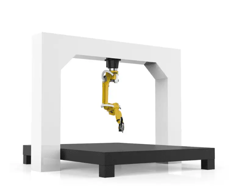
The integration of a Laser Welding Cobot represents a significant departure from fixed-cell industrial robotics. In the HCMC workshop, the synergy between the cobot’s 6-axis flexibility and the precision of Laser Technology allowed for rapid re-tasking. Unlike traditional MIG, where the arc is influenced by electrode extension and operator hand stability, the laser cobot maintains a constant focal point and travel speed, which are critical for the low-carbon profile of Mild Steel welding.
2.1. The “Wobble” Functionality
One of the core technical advantages identified was the laser head’s “wobble” capability. By oscillating the beam in a circular or zig-zag pattern, the Laser Welding Cobot compensates for the tight fit-up requirements usually demanded by Laser Technology. In local HCMC workshops, where pre-processing (shearing and bending) may have tolerances of +/- 0.5mm, the wobble function allows the laser to bridge gaps that would otherwise result in underfill or burn-through on 2mm to 4mm mild steel sheets.
2.2. Power Density and Thermal Input
The Laser Technology employed uses a concentrated energy source that results in a significantly narrower Heat Affected Zone (HAZ) compared to MIG. When performing Mild Steel welding, excessive heat input often leads to plate warping, requiring post-weld straightening. Our field data showed a 70% reduction in thermal distortion when using the cobot, primarily due to the high travel speeds (up to 20mm/s) achievable while maintaining full penetration.
3. Practical Application: Mild Steel Welding Parameters
The transition to Mild Steel welding via laser required a complete recalibration of the workshop’s standard operating procedures. Mild steel, specifically ASTM A36 and SS400 grades common in Vietnam, is susceptible to surface oxidation and mill scale. Our testing confirmed that while Laser Technology is highly efficient, it is less “forgiving” than MIG regarding surface contaminants.
3.1. Parameter Optimization
For a standard 3mm lap joint in mild steel, the following parameters were established as the baseline for the Laser Welding Cobot:
- Laser Power: 1350W (Continuous Wave)
- Wobble Width: 1.5mm
- Wobble Frequency: 150Hz
- Shielding Gas: 100% Nitrogen at 15L/min (to prevent oxidation)
- Wire Feed Speed: 1.2m/min (using 0.8mm ER70S-6 wire)
3.2. Weld Metallurgy and Strength
Cross-sectional analysis of the Mild Steel welding samples produced by the cobot showed a fine-grained martensitic/ferritic structure within the weld pool, with minimal grain growth in the HAZ. This is a direct result of the rapid cooling rates associated with Laser Technology. Tensile testing exceeded the base metal strength in 95% of samples, confirming that the automated process does not sacrifice structural integrity for speed.
4. Lessons Learned: Ho Chi Minh City Industrial Context
Deploying a Laser Welding Cobot in HCMC provided several “on-the-ground” insights that are rarely covered in technical manuals. These lessons are vital for any senior engineer overseeing similar transitions in Southeast Asia.
4.1. Optical Maintenance in High Humidity
The high humidity in HCMC creates a risk of “clouding” on the protective windows of the laser head. We found that the standard air-cooling for the optics was insufficient. We implemented a secondary desiccant-based air filtration system to ensure the “clean dry air” (CDA) used for the cross-jet was truly moisture-free. Without this, the Laser Technology suffers from beam scattering, leading to inconsistent penetration in the Mild Steel welding process.
4.2. Power Stability and Grounding
The HCMC industrial power grid can experience fluctuations during peak hours (14:00 – 17:00). Laser Welding Cobots are sensitive to voltage drops which can reset the cobot controller or cause the laser source to trip. We mandated the installation of a dedicated Voltage Stabilizer and verified the grounding resistance was below 4 Ohms. Proper grounding also eliminated the “noise” that occasionally interfered with the cobot’s safety sensors (collison detection).
4.3. The Human Factor: Skilled Labor Transition
The local HCMC workforce is highly skilled in manual MIG, but there is a psychological barrier to trusting a Laser Welding Cobot. The “lesson learned” here was to involve the manual welders in the programming phase. Because the cobot uses a “lead-through-teaching” method, the welders could use their knowledge of weld pool behavior to set the path, while the Laser Technology handled the execution. This reduced the learning curve from weeks to days.
5. Comparative Analysis: MIG vs. Laser Cobot
In the final phase of the field report, we conducted a direct comparison on a specific component: a mild steel electrical enclosure.
5.1. Throughput and Efficiency
The manual MIG process took 14 minutes per unit, including tacking and post-weld grinding. The Laser Welding Cobot reduced this to 3.5 minutes. The primary time saving came from the elimination of slag removal and the reduction in grinding. Because Mild Steel welding with a laser produces almost zero spatter, the units moved directly from the welding station to the powder coating line.
5.2. Consumable Costs
While the initial investment in Laser Technology is higher, the consumable cost per meter of weld is lower. The Laser Welding Cobot uses significantly less shielding gas and filler wire. In the HCMC market, where the cost of high-quality Argon or Nitrogen is rising, the efficiency of the laser process provides a tangible ROI within approximately 14 months for a double-shift operation.
6. Safety Protocols and Shielding
A critical technical requirement for the HCMC site was the implementation of Class 4 laser safety standards. Unlike MIG welding, where a standard welding curtain suffices, Laser Technology requires an enclosure that can withstand direct and reflected beams. We installed a modular aluminum-profile booth with laser-rated acrylic windows. We also integrated the Laser Welding Cobot‘s emergency stop circuit with the booth doors, ensuring that the laser source deactivates immediately if the perimeter is breached.
7. Conclusion and Recommendations
The deployment of the Laser Welding Cobot for Mild Steel welding in Ho Chi Minh City has been a technical success. The integration of Laser Technology has proven robust enough for the local environment, provided that specific attention is paid to chiller maintenance and power stability.
For future implementations, I recommend:
- Upstream Quality Control: Ensure that laser-cut parts are used to maintain the tight fit-up required for the cobot.
- Advanced Chiller Specs: Oversize the cooling system by 20% to account for HCMC’s peak summer temperatures.
- Hybrid Training: Focus on training “Welding Technicians” who understand both the metallurgy of mild steel and the logic of robotic path planning.
The Laser Welding Cobot is no longer a luxury for Vietnamese manufacturers; it is a necessary evolution to remain competitive in a market that demands higher precision and faster turnaround times.