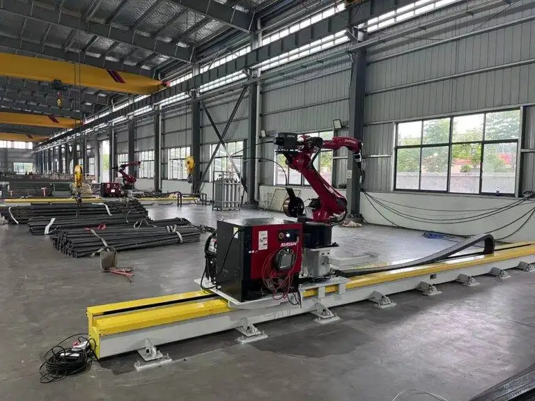
Robotic Welding Cell with 3D Vision positioning for Steel Structure

In this article
Integrating 3D Vision in Structural Steel Robotic Welding
In the domain of heavy steel fabrication, traditional automation often fails due to the lack of precision in large-scale components. Structural beams, gussets, and plates frequently exhibit dimensional variances exceeding one millimeter, which is sufficient to cause weld defects in fixed-path robotic systems. The implementation of a Robotic Welding Cell equipped with 3D Vision positioning transforms the process from a rigid sequence to an adaptive manufacturing operation.
The 3D vision system functions as the primary data input for the robot’s motion controller. By utilizing structured light or stereoscopic imaging, the system generates a high-density point cloud of the workpiece. This data is compared against the nominal CAD model in real-time, allowing the robot to calculate spatial offsets and adjust the welding path to account for fit-up gaps, pre-weld tacking inaccuracies, and thermal expansion during the process.
MAG Welding Process Optimization
The selection of Metal Active Gas (MAG) welding as the primary process for structural steel is driven by its high deposition rates and deep penetration capabilities. In an automated environment, the stability of the arc is paramount to ensuring weld integrity and minimizing post-weld cleanup.
Gas Selection and Shielding Stability
For structural steel, an 80/20 or 92/8 Argon/CO2 mixture is typically utilized. The 3D vision system allows the robot to maintain an optimal contact-to-work distance (CTWD), which is critical for gas shielding effectiveness. If the distance fluctuates, the turbulence in the gas flow can lead to porosity. Automated systems ensure that the nozzle remains perpendicular to the joint geometry, providing a consistent laminar flow of shielding gas even in complex fillet or groove welds.
Wire Feed and Deposition Metrics
Robotic MAG systems outperform manual operators by maintaining a constant wire feed speed synchronized with the travel speed. In structural applications, using a 1.2mm or 1.6mm solid wire allows for deposition rates exceeding 5kg/hr in a spray transfer mode. The 3D vision system monitors the joint volume, enabling the robot to adjust the travel speed or weave amplitude to fill varying gap sizes, ensuring that the weld throat thickness meets structural engineering specifications without over-welding, which wastes consumables and increases heat input.
Vision-Guided Positioning Mechanics
The “Search and Track” capability of a 3D vision sensor eliminates the need for expensive, high-precision jigging. In heavy structural steel, creating jigs that hold tolerances within 0.5mm is cost-prohibitive. Instead, the 3D sensor scans the joint before the arc is struck (pre-scan) and, in some advanced configurations, monitors the weld pool during the process (through-arc or laser tracking).
Point Cloud Registration
The robot controller uses algorithms to register the 3D point cloud against the global coordinate system of the cell. By identifying key features such as corners, edges, or bolt holes, the system calculates a 6-degree-of-freedom offset. This ensures that even if a 10-meter I-beam is placed with a 10mm deviation on the work table, the robot accurately locates the weld start and end points.
Handling Thermal Distortion
Welding large steel structures introduces significant heat, leading to warping. A vision-integrated cell can be programmed to re-scan specific segments of the assembly between weld passes. This adaptive behavior allows the system to compensate for “dynamic” changes in the geometry, a task that would require constant manual intervention in a standard robotic setup.
Maintenance Protocols for High-Availability Cells
The reliability of a 3D vision systems welding cell is dependent on a strict preventative maintenance (PM) schedule. Unlike manual welding stations, a robotic cell’s downtime affects the entire production line’s OEE (Overall Equipment Effectiveness).
Torch and Consumables Management
The welding torch requires daily inspection. Automated nozzle cleaning stations (reamers) should be integrated into the cell cycle to remove spatter buildup every 15-20 minutes of arc-on time. Contact tips should be replaced based on wire throughput metrics rather than failure modes to prevent arc instability. Furthermore, the wire liner must be blown out with compressed air weekly to remove shavings that cause feed motor strain.
Vision Sensor Calibration and Protection
The 3D vision sensor is a sensitive optical instrument operating in a harsh environment. It must be equipped with an automated shutter system or a high-pressure air curtain to prevent spatter and fumes from contaminating the lens. Monthly calibration checks using a reference gauge are necessary to ensure the coordinate transformation between the sensor and the robot flange remains accurate to within 0.1mm.
Labor ROI and Economic Analysis
The transition to robotic MAG welding is primarily justified through the optimization of labor resources and the reduction of rework. In many industrial regions, the scarcity of certified structural welders has driven labor costs to a level where the payback period for a robotic cell is frequently under 24 months.
Calculating the Return on Investment
To calculate ROI, an industrial engineer must look at the “Duty Cycle” improvement. A manual welder typically has an arc-on time of 20-30% due to fatigue, setup, and repositioning. A robotic cell with a dual-station positioner can achieve an arc-on time of 75-85%. By doubling or tripling the daily deposition volume, the cost per kilogram of deposited weld metal drops significantly.
Furthermore, the labor ROI is realized not just by replacing a welder, but by upskilling them. One operator can oversee two or three robotic cells, shifting their role from manual labor to “Cell Technician.” This reduces the headcount required for a specific tonnage of steel output while improving the consistency of the final product.
Quality Control and Rework Reduction
In structural steel, the cost of a weld failure in the field is catastrophic. Manual welding is prone to “human factor” defects such as lack of fusion or inconsistent penetration at the start/stop points. A MAG welding robot provides a digital record of every weld, including current, voltage, and gas flow rates. When combined with the precision of 3D vision positioning, the rate of weld rejection drops to near zero, eliminating the massive costs associated with grinding out and re-welding defective joints.
Conclusion
The deployment of a robotic welding cell with 3D vision positioning represents a fundamental shift in steel structure fabrication. By leveraging high-speed MAG processes and adaptive vision algorithms, manufacturers can overcome the limitations of part variance and thermal distortion. The result is a high-throughput, low-defect production environment that offers a clear path to profitability through optimized labor utilization and rigorous process control. For the industrial engineer, the focus remains on maintaining the synergy between optical precision and mechanical robustness to ensure long-term operational success.