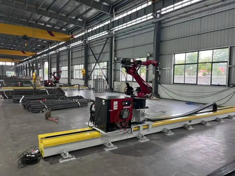
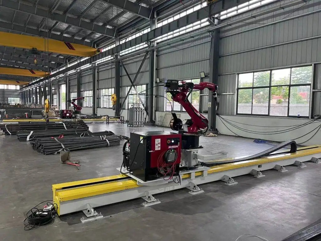
Automatic Girth Seam Welder with Narrow Gap welding for Oil & Gas Tanks
In this article
- Technical Superiority of Robotic Narrow Gap MAG Welding
- Robotic Motion Control and MAG Integration
- Maintenance Protocols for High-Duty Cycle Systems
- Consumable Management and Torch Geometry
- Wire Feed System and Conduit Integrity
- Quantifying Labor ROI and Operational Efficiency
- Deposition Rates and Throughput Analysis
- Defect Reduction and Quality Control
- Conclusion
Technical Superiority of Robotic Narrow Gap MAG Welding
In the construction of large-scale oil and gas storage tanks, the circumferential (girth) seam represents a critical path in the project schedule. Traditional manual or semi-automatic welding methods often rely on wide V-groove preparations, which require substantial volumes of filler metal and multiple passes. The industrial shift toward the Automatic Girth Welder (AGW) platform, integrated with robotic Narrow Gap MAG (Metal Active Gas) technology, has redefined the efficiency of these operations.
Narrow Gap welding (NGW) utilizes a square or near-square butt joint with a limited gap width, typically ranging from 9mm to 15mm depending on plate thickness. By utilizing Narrow Gap Welding techniques, the total cross-sectional area of the weld joint is drastically reduced. For an industrial engineer, this translates directly into reduced heat input, smaller heat-affected zones (HAZ), and a significant decrease in the number of weld passes required to achieve full penetration.
Robotic Motion Control and MAG Integration
The core of the modern AGW system is a motorized carriage that travels along the tank rim. The robotic component governs the torch oscillation, travel speed, and wire feed consistency. Unlike manual welding, where human fatigue leads to fluctuations in arc length, the robotic MAG system maintains a constant contact-to-work distance (CTWD). This precision is vital for the MAG process, which uses active shielding gases (typically CO2 or Argon/CO2 blends) to stabilize the arc and ensure deep penetration into the side walls of the narrow groove.

The Metal Active Gas (MAG) process is preferred in field conditions due to its high deposition rates and ability to handle the slightly oxidized surfaces common in carbon steel tank plates. Robotic integration allows for real-time monitoring of welding parameters—voltage, amperage, and wire feed speed—enabling closed-loop feedback systems to adjust for minor fit-up inconsistencies in the tank shells.
Maintenance Protocols for High-Duty Cycle Systems
From an engineering perspective, the reliability of an automated welding system is only as good as its maintenance program. Because AGW units operate in harsh field environments—exposed to dust, wind, and humidity—the maintenance schedule must be rigorous to prevent unplanned downtime.
Consumable Management and Torch Geometry
The narrow gap environment imposes strict physical constraints on the welding torch. The gas nozzle must be slim enough to reach the root of the joint without shorting against the side walls. Maintenance teams must inspect the contact tips every shift for “keyholing” or wear, which can cause arc instability. Replacing contact tips and gas diffusers preventively is a standard operating procedure to maintain weld quality standards required by API 650.
Wire Feed System and Conduit Integrity
The wire drive system is the heart of the robotic MAG setup. In Narrow Gap applications, even a micro-stutter in wire delivery can lead to sidewall lack-of-fusion. Engineers should prioritize the inspection of drive rolls for tension and alignment. The wire conduit or liner must be blown out with compressed air daily to remove shavings and debris. Using high-quality, matte-finished welding wire can also reduce the accumulation of copper flakes in the liner, extending the Mean Time Between Failures (MTBF) for the feeding assembly.
Quantifying Labor ROI and Operational Efficiency
The primary driver for adopting robotic AGW systems is the Labor ROI. In traditional tank construction, a crew of several highly skilled manual welders is required to complete a single girth seam on a 50-meter diameter tank. This process is not only slow but also prone to rework due to human error in multi-pass scenarios.
Deposition Rates and Throughput Analysis
A robotic MAG system can operate at a duty cycle of 80% or higher, whereas a manual welder typically achieves a 30-40% duty cycle due to the need for breaks, repositioning, and slag chipping. By automating the girth seam, the linear welding speed can increase from 10-15 cm per minute (manual) to over 50-70 cm per minute (automated), depending on plate thickness.
When calculating the Return on Investment, the following variables are considered:
- Reduction in total man-hours per tank.
- Decreased consumption of filler metal (up to 40% reduction in narrow gap joints).
- Lower shielding gas waste due to optimized flow rates and faster travel speeds.
- Elimination of scaffolding costs, as AGW units often include built-in operator cabins and weather protection.
Defect Reduction and Quality Control
Rework is one of the most significant hidden costs in industrial welding. Manual welding of girth seams often results in inclusions or porosity at the start/stop points. Robotic systems minimize these “cold starts” by performing continuous welds over much longer distances. The consistency of the robotic MAG process ensures that X-ray or ultrasonic testing (UT) pass rates remain high, often exceeding 98%. Avoiding the “cut-and-repair” cycle saves not only labor costs but also the expensive gases and consumables required for gouging and re-welding.
Environmental and Safety Considerations
Industrial engineers must also factor in the “Soft ROI” related to safety and ergonomics. Robotic AGW units remove the welder from the immediate proximity of welding fumes and intense heat radiation. By housing the operator in a carriage that travels with the machine, the risk of falls and repetitive strain injuries is mitigated. A safer work environment leads to lower insurance premiums and higher worker retention, which are critical in a market facing a shortage of certified pressure vessel welders.
Compliance with API and ASME Standards
Finally, the implementation of robotic Narrow Gap MAG welding must align with international codes such as API 650 (Atmospheric Storage Tanks) and ASME Section IX. The automation equipment must be capable of recording data logs for each weld, providing a “digital birth certificate” for the tank’s structural integrity. This level of traceability is increasingly demanded by oil and gas majors to ensure long-term asset reliability.
Conclusion
The integration of robotic Narrow Gap MAG welding into Automatic Girth Seam Welders represents a significant leap in industrial tank fabrication. By focusing on high deposition rates, rigorous maintenance of the wire feed path, and a clear understanding of labor ROI, industrial engineers can achieve faster project completion times while maintaining superior weld quality. The transition from manual V-groove welding to automated narrow gap processes is no longer just an option—it is a requirement for competitiveness in the modern energy infrastructure sector.