Automatic Girth Seam Welder with 5-Axis Beveling for Oil & Gas Tanks
In this article
Technical Overview of the Automatic Girth Seam Welder
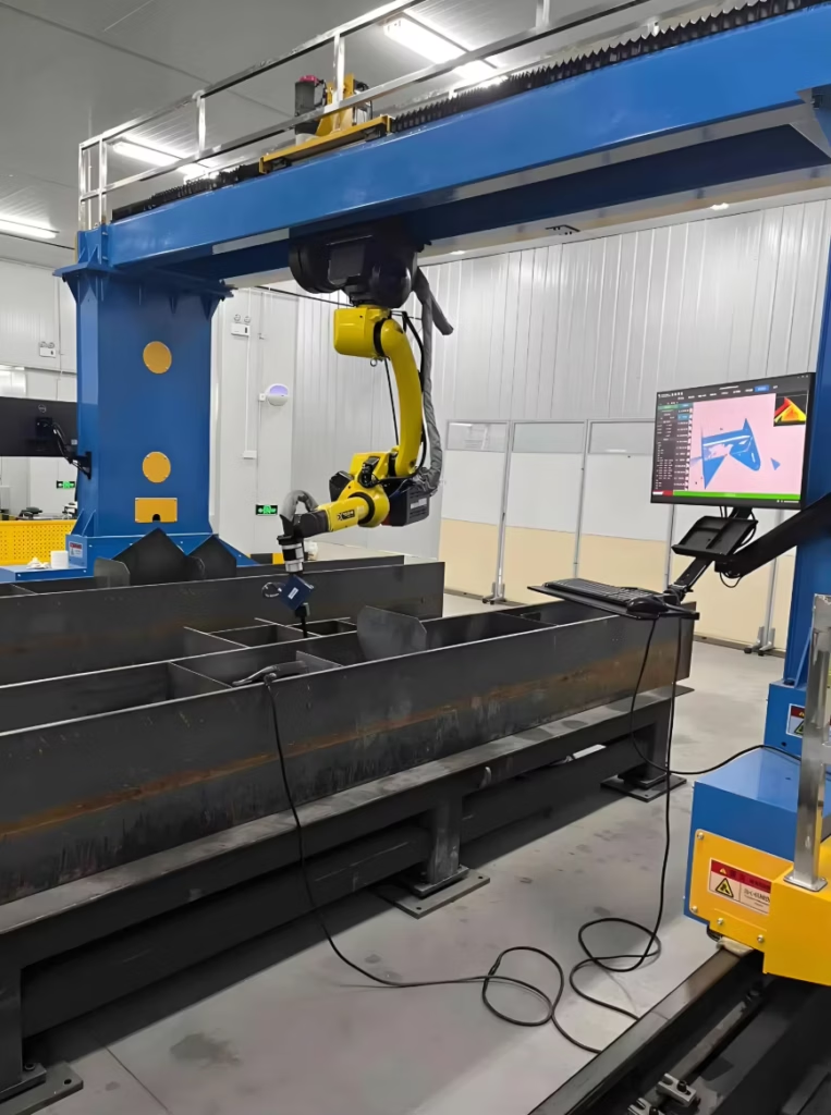
In the construction of large-scale storage tanks—compliant with API 650 and API 620 standards—the horizontal girth seam represents the most significant labor expenditure. Traditional manual welding in the 3 o’clock position is physically demanding and prone to inconsistencies. The Automatic Girth Seam Welder (AGW) addresses these inefficiencies by utilizing a self-propelled carriage that straddles the tank shell. By integrating a 5-axis robotic system, the equipment can manage complex edge geometries and maintain precise torch angles regardless of plate curvature or minor fit-up deviations.
The primary objective of this system is to transition from shielded metal arc welding (SMAW) to high-efficiency MAG welding process (GMAW). This shift allows for continuous wire feeding, eliminating the downtime associated with electrode changes and slag removal. The 5-axis functionality is critical here; it provides the necessary degrees of freedom to adjust the torch’s contact tip-to-work distance (CTWD) and travel angle in real-time, ensuring uniform penetration throughout the circumference of the vessel.
The Mechanics of 5-Axis Robotic Beveling Integration
Standard girth welders operate on a fixed path, which requires near-perfect plate alignment. However, in field conditions, gaps and offsets are inevitable. A robotic 5-axis system utilizes tactile or optical sensors to track the seam, allowing the torch to oscillate or tilt to compensate for variances. The “5-axis” designation refers to the X, Y, and Z linear movements combined with rotation (B-axis) and tilt (C-axis) of the welding head. This configuration is essential for executing multi-pass bevel fills where the root, hot pass, and cap must be laid with specific metallurgical properties.

When dealing with thick-walled oil tanks, 5-axis robotic beveling allows the system to perform “on-the-fly” adjustments to the weld pool dynamics. By modulating the torch angle relative to the gravity vector, the system prevents the molten metal from sagging—a common defect in horizontal position welding. This precision ensures that the weld profile meets stringent radiographic testing (RT) requirements on the first pass, significantly reducing the cost of rework.
MAG Welding Parameters and Metallurgical Integrity
The selection of the MAG process over flux-cored arc welding (FCAW) or SMAW is driven by deposition efficiency and clean-up requirements. In an industrial AGW setup, we typically utilize a 1.2mm to 1.6mm solid wire with an Argon-CO2 shielding gas mixture. The 5-axis head manages the spray transfer mode, which is characterized by a stable, spatter-free arc and high metal recovery rates.
Key technical parameters for an optimized girth seam include:
- Wire Feed Speed: 8.5 – 12.0 m/min
- Voltage: 24V – 32V (Pulsed current preferred for heat input control)
- Travel Speed: 400 – 800 mm/min (depending on plate thickness and pass number)
- Gas Flow: 15 – 25 L/min to counteract wind interference in field environments
By using a pulsed MAG waveform, the robotic controller can minimize the heat-affected zone (HAZ), preserving the mechanical properties of the high-tensile steel used in tank shells. This is a critical factor in maintaining the fracture toughness required for cryogenic or high-pressure storage applications.
Labor ROI and Operational Throughput
The financial justification for adopting an AGW system is rooted in the Labor ROI. Manual welding of a 50-meter diameter tank requires a large crew of highly skilled welders, often working in multiple shifts to meet project deadlines. An AGW system, managed by a single technician, can replace the output of four to six manual welders.
Consider the following productivity comparison for a 20mm thick shell plate:
| Metric | Manual (SMAW/FCAW) | Robotic AGW (MAG) |
|---|---|---|
| Deposition Rate (kg/hr) | 1.5 – 2.2 | 5.5 – 8.0 |
| Arc-On Time (Duty Cycle) | 30% – 40% | 75% – 85% |
| Linear Meters per Day | 12 – 18m | 60 – 90m |
The return on investment is realized not only through direct labor savings but also through the reduction of “auxiliary costs.” These include scaffolding requirements, PPE consumption, and the logistical overhead of managing a large field crew. Furthermore, the consistency of the robotic MAG process yields a defect rate typically under 1%, compared to the 5-7% industry average for manual field welds. Reducing the need for gouging and re-welding saves hundreds of man-hours over the course of a single project.
Maintenance Protocols for High-Uptime Systems
To sustain the high duty cycles offered by robotic AGW systems, a rigorous preventive maintenance schedule is mandatory. Industrial engineers must account for the harsh environments of tank farms, which include dust, humidity, and temperature fluctuations. The MAG system’s wire delivery path is the most common point of failure.
Daily and Weekly Maintenance Tasks
The contact tip must be inspected every 4 hours of arc-on time. Even slight erosions in the tip diameter can cause arc instability and degrade the 5-axis precision. Liners should be blown out with compressed air daily to remove copper flaking and dust that increase friction in the wire drive motor. The robotic arm’s 5-axis joints require periodic calibration to ensure the coordinate system has not drifted due to the vibrations of the carriage movement.
Long-term Reliability (MTBF)
The Mean Time Between Failures (MTBF) for the power source and the 5-axis drive motors is generally 10,000+ hours, provided the cooling systems are maintained. In MAG welding, the water-cooling unit for the torch must be monitored for flow rate and pH levels to prevent internal corrosion of the robotic head. Failure to maintain the cooling system can lead to catastrophic torch failure, resulting in significant project delays.
Conclusion: Systemic Efficiency in Tank Fabrication
The integration of an Automatic Girth Seam Welder with 5-axis robotic capabilities represents a shift from craft-based labor to a process-controlled manufacturing environment. By focusing on Duty cycle optimization and the inherent advantages of the MAG process, industrial firms can significantly compress project timelines. The capital expenditure of the robotic system is typically recouped within the first two major tank projects through reduced labor hours and superior weld quality. As the oil and gas sector continues to face a shortage of skilled manual welders, automation via 5-axis MAG systems is no longer an optional upgrade but a strategic necessity for maintaining competitive throughput.