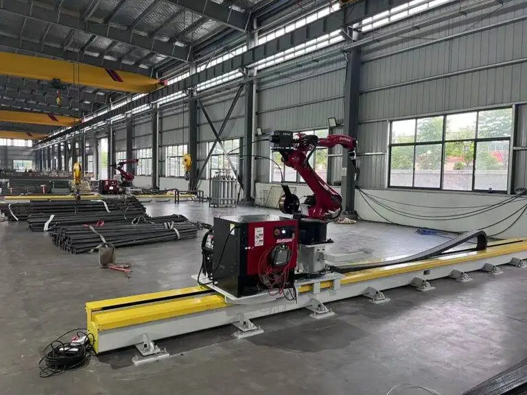
Automatic Girth Seam Welder with 3D Vision positioning for Wind Tower fabrication
In this article
Optimizing Wind Tower Throughput via Robotic Girth Seam Welding
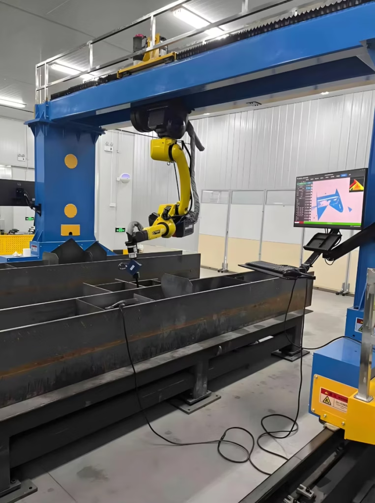
In the fabrication of utility-scale wind towers, the girth seam remains the most critical bottleneck. Industrial engineers prioritize the transition from manual submerged arc or semi-automatic processes to fully integrated 3D vision-guided welding systems. This shift is driven by the need for geometric precision in large-diameter sections, where even minor fit-up deviations can lead to catastrophic failure or costly rework. A robotic cell equipped with 3D vision does not merely follow a path; it dynamically adapts to the groove geometry in real-time, ensuring consistent penetration and bead profile across the entire circumference.
The Role of 3D Vision in Adaptive Positioning
Traditional Robotic Welding relies on fixed coordinates, which are insufficient for wind tower sections that often exceed 4 meters in diameter. Material deformation, gravity-induced sagging, and tack-welding variances create a non-linear path. The implementation of 3D vision sensors allows the system to map the seam profile milliseconds before the arc is struck.
By utilizing structured light or laser-triangulation sensors (strictly for measurement, not cutting), the system calculates the volume of the V-groove or J-groove. This data is fed into the robot controller, which adjusts the wire feed speed, travel speed, and torch oscillation. This adaptive capability ensures that the Metal Active Gas (MAG) process maintains the required fill volume, even when the gap width varies by several millimeters.

MAG Process Efficiency in Heavy-Gauge Steel
The selection of the MAG process over other methods in wind tower girth seams is predicated on deposition rates and metallurgical integrity. Utilizing high-performance power sources, the robotic system can execute multi-pass welds with high duty cycles. Unlike manual operators who must stop for repositioning and fatigue management, the robot maintains a continuous arc.
Deposition and Interpass Control
For sections with wall thicknesses ranging from 20mm to over 50mm, the robotic MAG system manages the heat input with extreme precision. The 3D vision system monitors the height of each layer, ensuring the interpass temperature remains within the specified Welding Procedure Specification (WPS). This level of control minimizes the Heat Affected Zone (HAZ) and prevents the grain growth that can weaken the structural integrity of the tower.
Labor ROI: Quantifying the Shift to Automation
The primary driver for robotic investment is the optimization of the arc-on time. In a manual welding environment, a skilled welder typically achieves an arc-on time of 25% to 30% due to setup, fatigue, and environmental factors. A robotic girth seam welder increases this metric to 75% or higher.
Direct Labor Cost Reduction
By deploying a vision-guided system, a single technician can oversee two or even three welding cells. This removes the “one-man-one-arc” limitation. When calculating ROI, the engineer must factor in the reduction of secondary operations. Because the 3D vision ensures perfect alignment, the incidence of weld defects such as porosity, undercut, or incomplete fusion is reduced by approximately 90%. This eliminates the massive costs associated with gouging out and repairing defects in heavy-gauge steel.
Consistency as a Capital Asset
Automation provides “calculated predictability.” For a project manager, knowing that a girth seam will be completed in exactly 4.5 hours—regardless of the time of day or operator skill level—allows for tighter scheduling of the downstream assembly stages. This predictability reduces the work-in-progress (WIP) inventory on the shop floor, accelerating the overall factory throughput.
Maintenance Framework for High-Availability Systems
To sustain the ROI of a robotic girth welder, a rigorous preventative maintenance schedule is non-negotiable. Unlike manual equipment, a robot failure halts the entire production line.
Consumable Management
The most frequent point of failure in MAG welding is the torch assembly. Automated torch cleaning stations must be integrated into the cell to clear spatter every few cycles. Contact tips should be replaced based on wire throughput metrics rather than failure. 3D vision cameras require clean lenses and calibrated sensors; a daily check-off list for lens clarity and sensor alignment is essential to prevent “vision drift,” where the robot begins to misinterpret the seam geometry.
Mechanical and Electronic Calibration
The robotic arm and the rotators (turning rolls) must be synchronized. Periodically, the industrial engineer must audit the encoder feedback from the turning rolls to ensure the surface speed of the tower matches the robot’s programmed travel speed. Discrepancies here lead to inconsistent bead width and potential structural weaknesses.
Standardizing the Future of Tower Fabrication
As wind towers grow in height and weight, the demands on girth seams become more stringent. The integration of 3D vision-guided MAG welding represents the pinnacle of current industrial engineering application in this sector. By focusing on the removal of human variability and the maximization of mechanical duty cycles, manufacturers can achieve a level of quality and cost-efficiency that manual processes cannot mirror.
Ultimately, the transition to robotic welding is not just a technological upgrade; it is a strategic necessity. The data harvested from the 3D vision system provides a digital twin of every weld performed, offering a level of traceability and quality assurance that satisfies the most demanding offshore and onshore engineering standards. The ROI is found not just in the wages saved, but in the total elimination of variability in one of the most demanding welding applications in modern industry.