Fiber Laser Cutting Parameters: Power, Gas, Focus, Height
In this article
- Key Takeaways
- What Are the Main Fiber Laser Cutting Parameters?
- Why Does Focus Position Cause Dross?
- How Does Assist Gas Pressure Change the Cut Edge?
- What Nozzle Diameter and Cutting Height Should I Use?
- How Do I Pierce Thick Carbon Steel Without Waiting?
- What Parameters Work for 3 mm Stainless Steel and How to Tune…
- Starting parameter sets
- Tuning order
- What This Means for Buyers
- Frequently Asked Questions
- What are the main fiber laser cutting parameters?
- How do I stop dross on 3 mm stainless steel?
- What nozzle diameter should I use?
Fiber laser cutting parameters are the settings for laser power, assist gas pressure, focus position, nozzle diameter, standoff height, and cutting speed that must match the material and thickness. The goal is clean edges with no heavy dross, a narrow kerf, and stable piercing. PCL Group builds and commissions CNC fiber laser cutters, and we give operators these starting values so they can reach that state in minutes, not hours.
Key Takeaways
- Cut quality is set by matching power, gas pressure, speed and focus, not by any single parameter.
- For 3 mm 304 stainless on a 3 kW laser, nitrogen at 14 bar gives a bright edge; optimized compressed air at 10 bar gives a light-straw structural edge.
- Focus position needs to sit at the surface for carbon steel and about half the plate thickness below the surface for stainless steel.
- Nozzle size and standoff follow material thickness: thinner sheet uses 1.0–1.2 mm nozzles and 0.7–1.2 mm height; thick plate uses 2.0–2.5 mm and more height.
- Thick carbon steel piercing on a 1.5 kW machine can be cut from 10 s to 3.5 s with a three-stage focus and gas sequence.
What Are the Main Fiber Laser Cutting Parameters?
Five settings interact on every cut: laser power, assist-gas pressure, focus position, nozzle diameter and standoff height, and cutting speed. Change one and the others need adjustment. A clean cut is a balance; setting one value to an extreme will not fix a dross problem.
Power sets how much energy reaches the kerf. Too little power leaves incomplete penetration and dross; too much power overburns the edge. Gas pressure clears molten metal and, with oxygen, feeds the exothermic reaction in carbon steel. Focus position moves the beam waist inside the plate. Nozzle diameter and standoff control gas delivery to the kerf. Speed sets the heat input per millimetre.
Cut-surface finish, dross, full penetration and dimensional accuracy are produced by the combination of parameters, not one alone. Material flatness, surface rust, nozzle concentricity and nozzle wear also change the result. Check those mechanical items before changing laser settings.
Why Does Focus Position Cause Dross?
Focus position is the distance from the laser focal point to the workpiece surface. A positive offset puts the focal point above the sheet and a negative offset sets it below the surface. This moves where the beam waist sits inside the material.
A focus set too high concentrates the beam energy toward the top of the plate and leaves less energy at the bottom of the kerf, so the bottom edge can show dross or incomplete cuts. Set too low, the beam waist moves deeper and the bottom gets more energy, which can overheat the lower edge. For carbon steel, starting at the plate surface usually gives the best cut quality. For stainless steel, start at about half the plate thickness below the surface. On 3 mm 304 stainless with a 3 kW laser and optimized air, the focus offset is -1.2 mm. The beam waist sits deeper, lowers the top-edge surface temperature, and keeps the oxide film thin.
How Does Assist Gas Pressure Change the Cut Edge?
Assist gas blows away molten slag and cools the material. Oxygen also reacts with carbon steel, adding heat and allowing lower laser power. Nitrogen and air work by melt-and-blow for stainless steel and aluminium.
Gas pressure that is too high creates vortices on the surface, weakens melt removal, widens the kerf and makes the cut face rough. Too low pressure leaves molten material in the kerf and dross on the lower surface. For 3 mm 304 stainless with nitrogen, we start at 14 bar. For optimized compressed air on the same material, we drop to 10 bar because lower pressure reduces turbulence and air entrainment, which keeps the oxide film thin.
Oxygen cutting of carbon steel is a low-pressure process: recommended settings fall from 8–10 bar on 0.8–1.5 mm plate down to 4–6 bar on 12–16 mm plate. Do not use high-pressure oxygen on thin steel; it causes roughness and wide kerf.
What Nozzle Diameter and Cutting Height Should I Use?
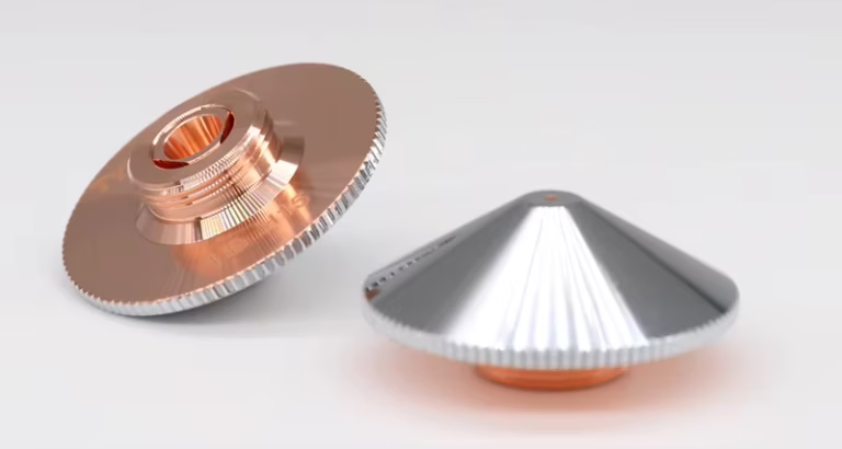
The nozzle is the final passage for the beam and the gas. A small nozzle (1.0 mm) makes a fast, concentrated gas jet for thin sheet. A large nozzle (1.5 mm or 2.0 mm) moves more gas volume to clear a deep kerf in thick plate.
Cutting height is the distance from the nozzle tip to the workpiece. Too low and the nozzle hits the plate or gets splashed with molten metal; too high and the gas expands, loses pressure, leaves dross and widens the kerf. On 3 mm stainless with a 1.5 mm nozzle, standoff is 0.8–1.0 mm depending on gas. On 1.5 mm stainless with a 1.2 mm nozzle, standoff is 0.7–0.8 mm.
For carbon steel with oxygen, use this starting table. All values assume clean plate and correct focus; adjust pressure within the range to get clean separation and minimal dross.
| Carbon steel thickness | Nozzle diameter | Cutting height | Oxygen pressure |
|---|---|---|---|
| 0.8–1.5 mm | 1.0 mm | 0.8–1.2 mm | 8–10 bar |
| 2.0–3.0 mm | 1.2 mm | 1.0–1.5 mm | 7–9 bar |
| 4.0–6.0 mm | 1.5 mm | 1.2–1.8 mm | 6–8 bar |
| 8.0–10.0 mm | 2.0 mm | 1.5–2.0 mm | 5–7 bar |
| 12.0–16.0 mm | 2.5 mm | 1.8–2.5 mm | 4–6 bar |
Do not use a 1.2 mm nozzle on 6–8 mm carbon steel; it cannot supply enough gas force, so the bottom edge will carry severe dross. On 1–2 mm stainless, do not use a 1.5 mm nozzle because gas consumption is excessive and the edge taper increases.
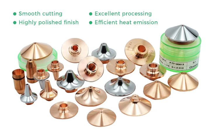
In production, incorrect cutting height is a main cause of nozzle damage. Keeping the correct standoff increases nozzle and protective window life by more than 50% and reduces post-processing time by 40% by almost eliminating bottom-edge dross. It also saves gas: using the right smaller nozzle for thin sheet cuts gas consumption by about 15%.
How Do I Pierce Thick Carbon Steel Without Waiting?
Piercing thick carbon steel with low power is slow because the laser needs time to build heat and start the oxygen-assisted reaction. On a 15 mm plate with a 1.5 kW fiber source, a safe piercing wait is 10 s per hole. If a part has 50 holes and 60 s of contour cutting, that is 500 s of piercing and a total cycle of 560 s; 89% of the time is waiting.
A three-stage sequence replaces that wait. It uses focus position and gas pressure in stages to first heat the surface, then drill the core, then clear the hole. The sequence on 15 mm carbon steel with 1.5 kW is:
- Stage 1 – heat accumulation. About 1 s at focus offset -1 mm with high gas pressure to heat the surface and start the reaction.
- Stage 2 – core drilling. About 2 s at focus offset -5 mm with low, controlled gas pressure to maintain a molten channel in the steel core.
- Stage 3 – clearing. About 0.5 s at focus offset -3 mm with gas pressure instantly raised to 100% to clear slag and detach the hole.
This cuts piercing time from 10 s to 3.5 s, a 65% reduction, and raises throughput on the example part from about 6.4 to 15.3 parts per hour, a 139% gain. On a 3 kW source, piercing the same 15 mm plate takes 1.5–2.5 s. On 6 kW and above it takes under 1.0 s. Higher power replaces waiting time and chemical energy with pure laser heat, and gives more stable piercing with less backspatter.
Engineer’s tip: If you still see backspatter on 15 mm carbon steel piercing, increase laser power instead of increasing wait time. A 3 kW source pierces the same plate in 1.5–2.5 s and reduces operator skill dependence.
What Parameters Work for 3 mm Stainless Steel and How to Tune Them?
For 3 mm 304 stainless on a 3 kW fiber laser, two parameter sets are useful: nitrogen for a bright, silver-white edge, and optimized compressed air for a light-straw structural edge. The values are starting points; verify with test cuts on your material and gas purity.
Starting parameter sets
| Material / thickness | Laser power | Assist gas | Gas pressure | Nozzle diameter | Standoff | Focus offset | Cutting speed |
|---|---|---|---|---|---|---|---|
| 3.0 mm 304 stainless | 3 kW | Nitrogen, 99.995% | 14 bar | 1.5 mm | 1.0 mm | -0.8 mm | 8.5 m/min |
| 3.0 mm 304 stainless | 3 kW | Optimized compressed air | 10 bar | 1.5 mm | 0.8 mm | -1.2 mm | 10.5 m/min |
| 1.5 mm 304 stainless | 3 kW | Nitrogen | 14 bar | 1.2 mm | 0.8 mm | -0.3 mm | 22 m/min |
| 1.5 mm 304 stainless | 2.5 kW | Optimized compressed air | 9 bar | 1.2 mm | 0.7 mm | -0.6 mm | 32 m/min |
Read each row as a complete set. If you change gas from nitrogen to air, do not keep the nitrogen focus and pressure. On the optimized air row, power stays at 3 kW for 3 mm, but speed rises to 10.5 m/min and pressure drops to 10 bar. For the 1.5 mm air row, laser power is reduced to 2.5 kW to limit heat input.
Nitrogen gives edge roughness Ra 4–6 µm and a scrap rate of 0.2%. Optimized air gives Ra 6–8 µm and scrap rate 0.5%. The edge is light straw because the oxide layer stays 5–10 nm; it passes a 24 h ASTM B117 salt-spray test after passivation and welds without porosity. For visible surfaces, continue to use nitrogen. For food-contact parts, a dark oxide layer is not acceptable, so use nitrogen or keep the air edge light straw.
Engineer’s tip: When switching from nitrogen to compressed air on 304 stainless, do not reuse the nitrogen focus and pressure. Load the air parameter set, lower pressure to 10 bar, move the focus to -1.2 mm, and raise speed from 8.5 to 10.5 m/min on 3 mm. This keeps the oxide film light straw and removable with a single wire-brush pass.
Tuning order
- Measure power. Put a power meter on the cutting head and confirm the specified laser power. Beam quality (M² or BPP) requires a beam profiler. If power is low, no other setting will fix dross.
- Check focus offset. Use the material library in the CNC controller and confirm the focus position. For carbon steel start at the surface; for stainless steel start at half the plate thickness. On a 3 kW machine cutting 3 mm stainless, the focus offset is -0.8 mm with nitrogen and -1.2 mm with air.
- Set gas pressure. Use the pressure for the material and thickness. For carbon steel with oxygen, use the low-pressure table. For stainless with nitrogen, start at 14 bar; for air, 10 bar. Check the gas purity: nitrogen must be 99.995% for bright edges.
- Set speed. Enter the cutting speed from the parameter table. Watch the spark pattern: with oxygen on carbon steel, sparks should exit the bottom kerf; with nitrogen on stainless, the cut line should stay clean and bright with no heavy slag ejection.
- Check nozzle and standoff. Use the correct nozzle diameter and standoff. On 3 mm stainless the nozzle is 1.5 mm; standoff is 0.8–1.0 mm. On 1.5 mm stainless, nozzle is 1.2 mm and standoff 0.7–0.8 mm. Inspect the nozzle for roundness and concentricity before each shift.
After the first test cut, measure edge roughness and look at dross. Small adjustments to focus and speed are usually enough. A parameter that is far out of range usually means a mechanical or gas-purity problem.
Safety: Assist gas pressures of 10–14 bar are dangerous. Never point a nozzle at skin or clothing. Compressed air must be clean and dry: a 0.01 µm coalescing filter and a desiccant dryer to -20°C pressure dew point prevent oil mist and water vapor from entering the cutting head. Fumes from cutting stainless steel contain chromium and nickel; extract them at the source. Copper and aluminium reflect laser light; use correct focus and shielding if your machine requires it.
How to use these numbers: All values above are starting points from commissioning sheets. Your material grade, gas purity, nozzle wear, laser source condition and machine dynamics will shift the optimum. Cut a 50 mm straight line, measure edge roughness and bottom dross, then adjust one parameter at a time. The best setting is the one that repeats on the next sheet.
What This Means for Buyers
If you cut stainless steel and need bright visible edges, a 3 kW fiber laser with nitrogen gives Ra 4–6 µm and a 0.2% scrap rate. If most of your parts are structural and you want to avoid nitrogen cost, an optimized compressed-air parameter set on the same machine gives Ra 6–8 µm and a 0.5% scrap rate, with the edge suitable for welding and passivation. The machine controller should let you switch between gas sources without hardware changes.
For carbon steel, do not buy a low-power machine for thick plate if you pierce many holes. A 1.5 kW source can cut 15 mm plate but spends 10 s piercing unless you use the three-stage sequence. A 3 kW or 6 kW source pierces the same hole in under 2.5 s or under 1 s and cuts 20 mm and thicker reliably. The price difference is paid back in throughput if your parts have many pierces.
Ask the machine supplier for the parameter library and the gas-quality requirements. Check the nozzle selection table; it should be in the controller. Then verify with test cuts before accepting the machine. We publish starting parameters for every machine we build. See our fiber laser cutting machines and CNC plate cutters for controller and gas manifold options.
Frequently Asked Questions
What are the main fiber laser cutting parameters?
Laser power, assist gas pressure, focus position, nozzle diameter, cutting height (standoff), and cutting speed. They must match the material and thickness. Changing one usually requires checking the others.
How do I stop dross on 3 mm stainless steel?
On a 3 kW laser, set focus to -0.8 mm with nitrogen at 14 bar and speed 8.5 m/min, or use optimized air: focus -1.2 mm, air 10 bar, speed 10.5 m/min. Too-low gas pressure leaves dross; too-high pressure causes turbulence and rough edges.
What nozzle diameter should I use?
For sheet below 3 mm, use a 1.0–1.2 mm nozzle. For 3–8 mm, a 1.5 mm nozzle usually balances gas jet and volume. Above 8 mm, use 2.0 mm or larger to clear the deep kerf. Check cutting height too: low causes nozzle damage, high loses pressure.
Can I use compressed air instead of nitrogen on stainless steel?
Yes, for structural parts. On 3 mm 304 with a 3 kW laser, optimized air gives a light-straw edge with Ra 6–8 µm, provided the air is dry and clean. The edge passes salt-spray and weld tests after passivation. For visible or food-contact surfaces, use nitrogen.
Why is piercing thick carbon steel so slow?
Low-power lasers need time to heat the plate and start the oxygen reaction. On 15 mm plate at 1.5 kW, a safe wait is 10 s per hole. A three-stage focus and gas sequence cuts that to 3.5 s. Higher power (3 kW or 6 kW) pierces in 1.5–2.5 s or under 1.0 s.
What gas pressure should I use for carbon steel?
Oxygen cutting is low-pressure. Start at 8–10 bar for 0.8–1.5 mm plate, 7–9 bar for 2–3 mm, 6–8 bar for 4–6 mm, 5–7 bar for 8–10 mm, and 4–6 bar for 12–16 mm. Use the corresponding nozzle diameter and cutting height from the selection table.